Corner-scales: the desk test
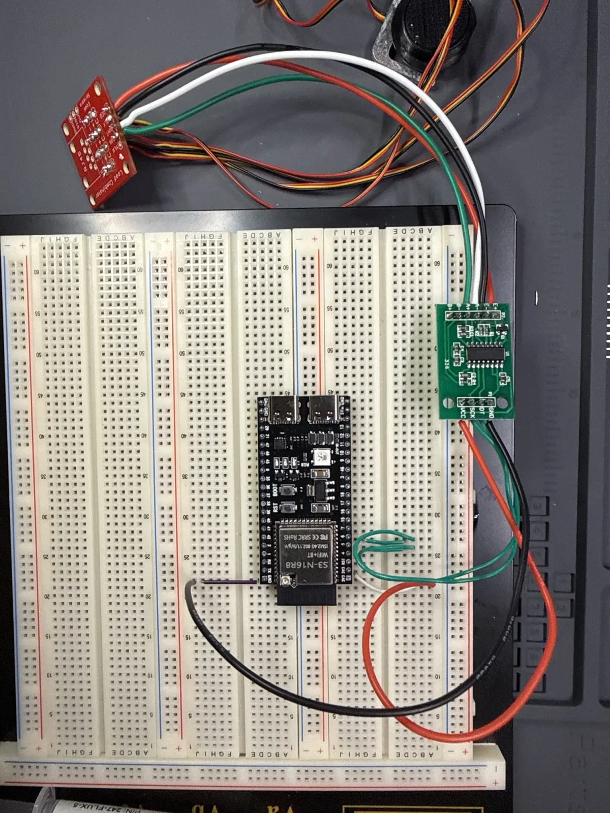
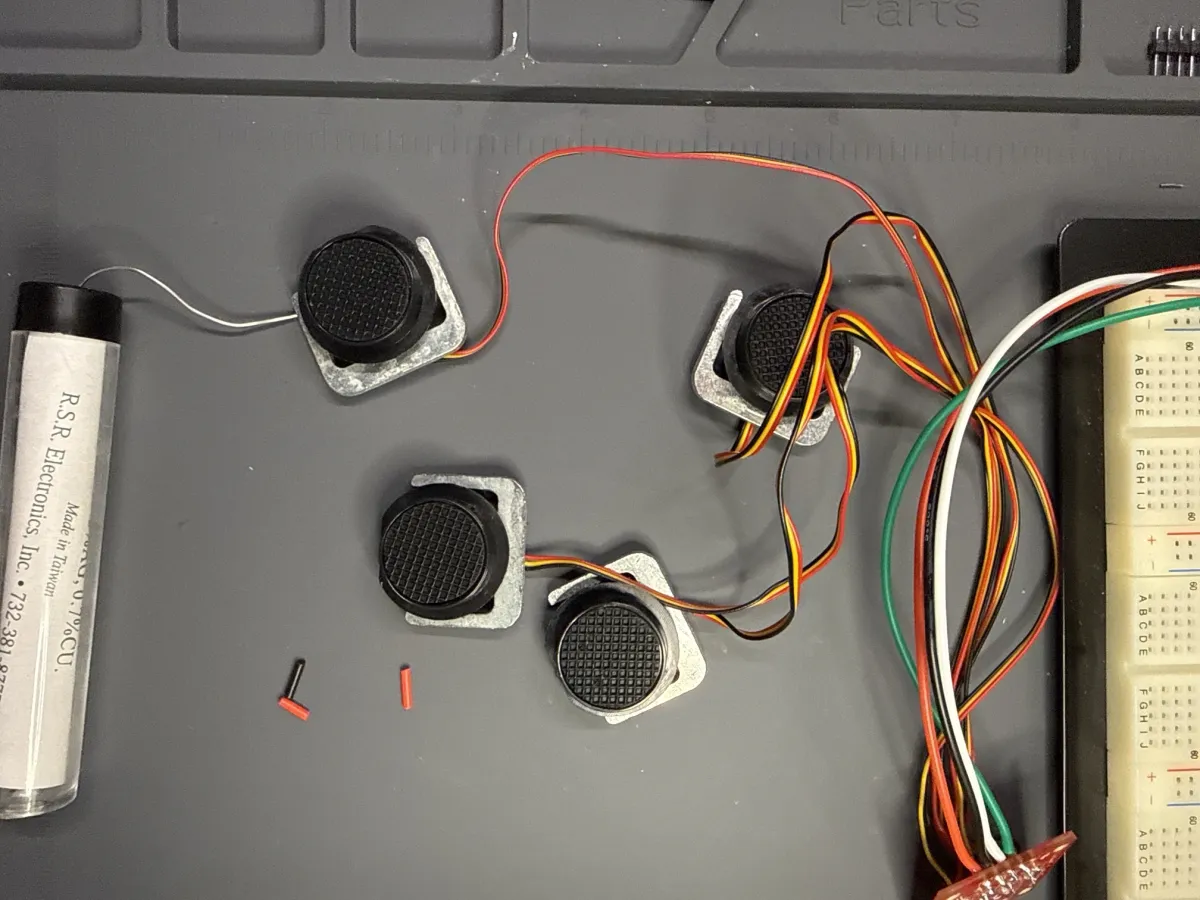
Four load cells, a SparkFun Combinator, a generic HX711 and an ESP32-S3, wired up on the desk until pressing each cell moved the number.
The parts for corner-scales arrived, so I started on the electronics before a trip to the hardware store for plywood. The goal for this step is to press a load cell and see the reading change on the serial console.
The plan
For this test everything sits on the desk, connected with short wires. No enclosure yet.
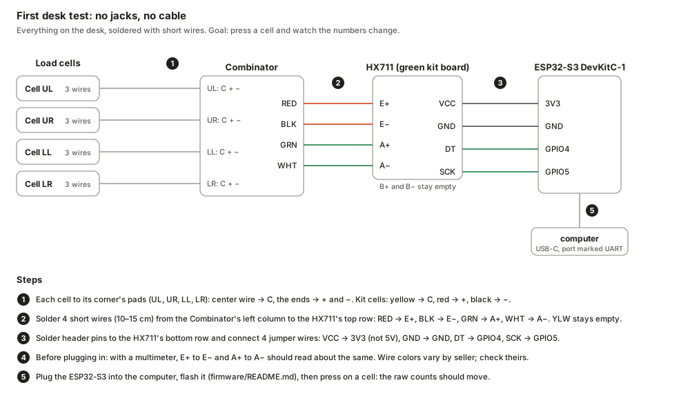
- Four 50 kg load cells. Each has two strain gauges and three wires.
- SparkFun Load Sensor Combinator. Wires the four cells together into one bridge the HX711 can read.
- HX711. Amplifies the bridge’s few millivolts and turns them into a 24-bit number, about 10 times a second.
- ESP32-S3. Reads that number and turns it into kilograms.
The HX711
Instead of the SparkFun board, I’ll be using the HX711 included in the load cell kit.
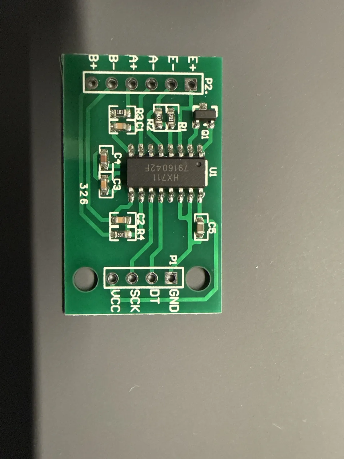
Its pins are labeled E+, E−, A+, A− instead of by wire color, and it has one power pin, VCC. VCC also sets the logic level, so it goes to the ESP32’s 3.3 V, not 5 V. Channel B isn’t used.
I soldered screw terminals on both rows so I can rewire without the iron. My first pass was lumpy, and two joints on the top row looked like they might be touching:
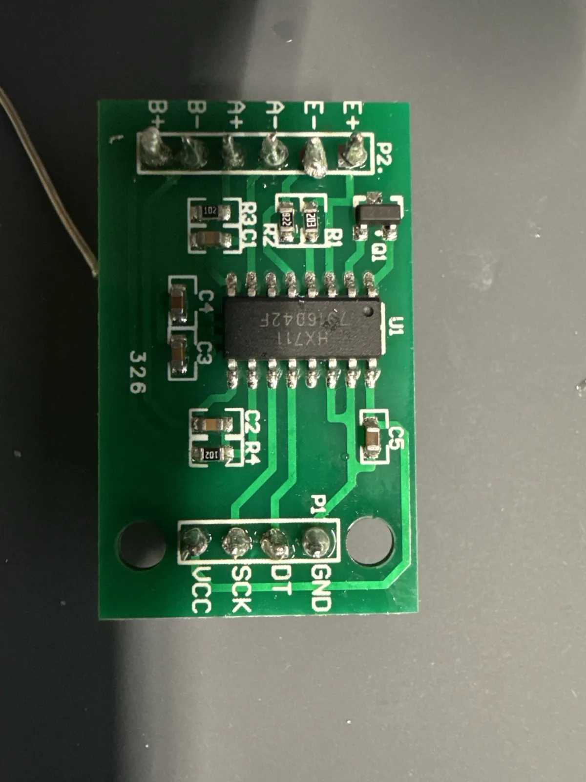
I reflowed them with a bit of flux:
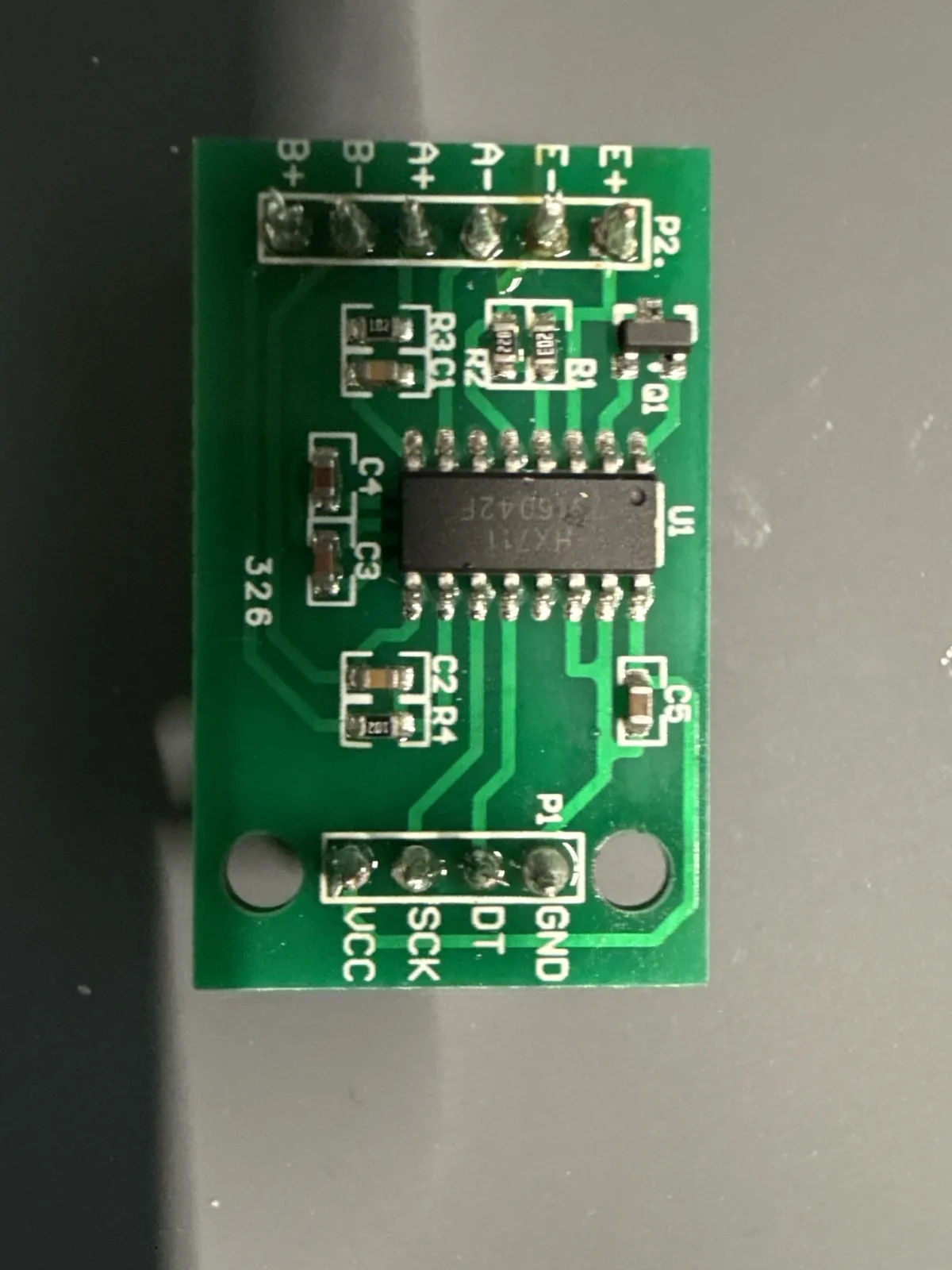
I checked neighboring pins with the multimeter’s continuity mode. No beeps, so no shorts.
Finding the center wire
The Combinator has three pads per corner (UL, UR, LL, LR), labeled C, + and −.
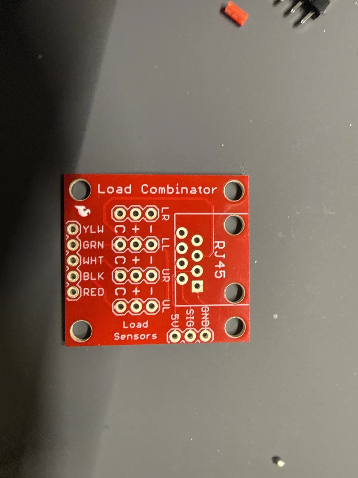
C is the cell’s center wire. Each cell is two resistors in a row, with a wire at each end and one in the middle. Wire colors vary by seller, so measure instead of guessing. On my cells (red, yellow, black):
| Pair | Reading |
|---|---|
| red–black | ~2 kΩ |
| red–yellow | ~1 kΩ |
Red–black reads twice as much, so those are the two ends and yellow is the center. On all four cells: yellow → C, red → +, black → −.
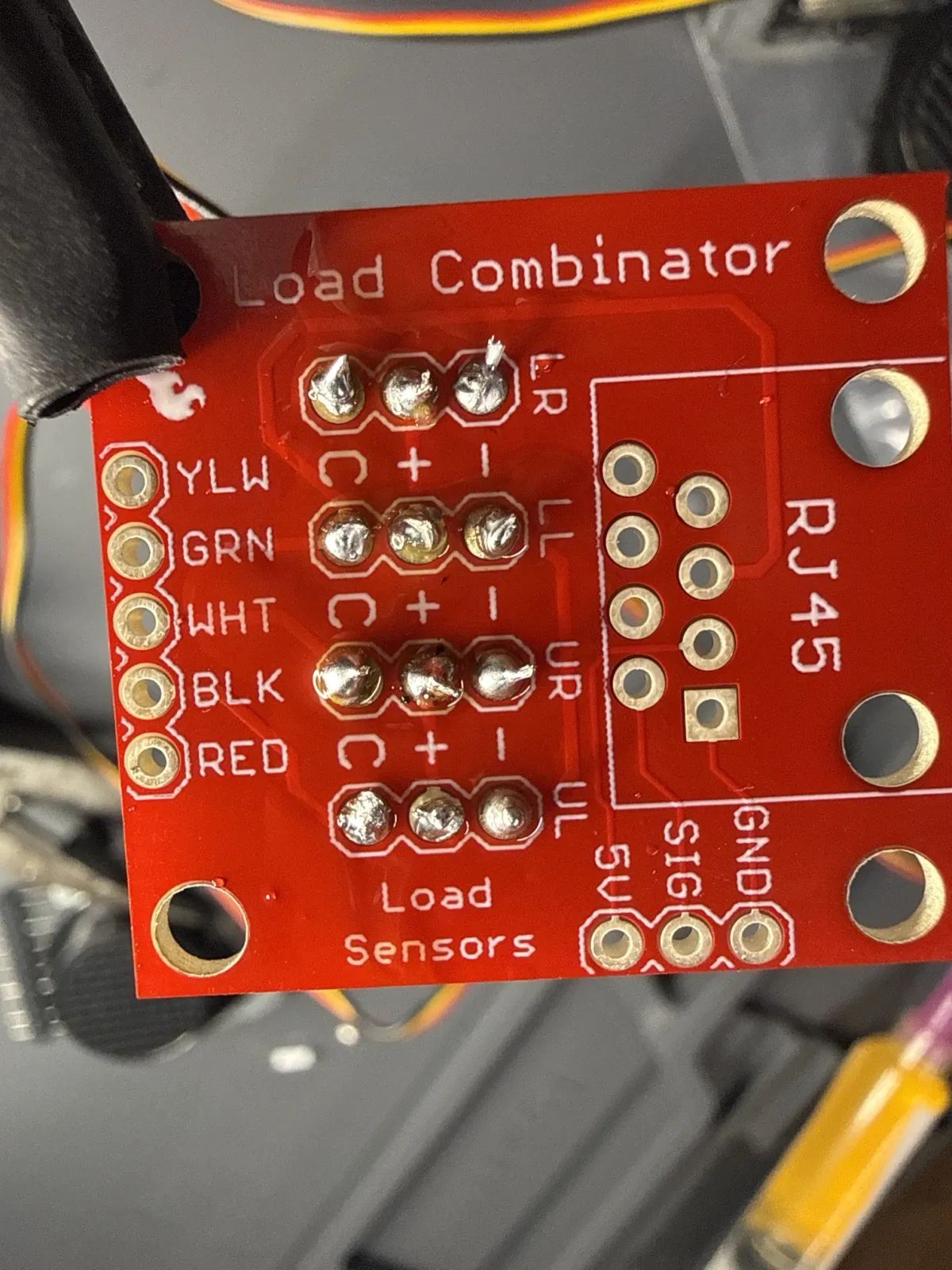
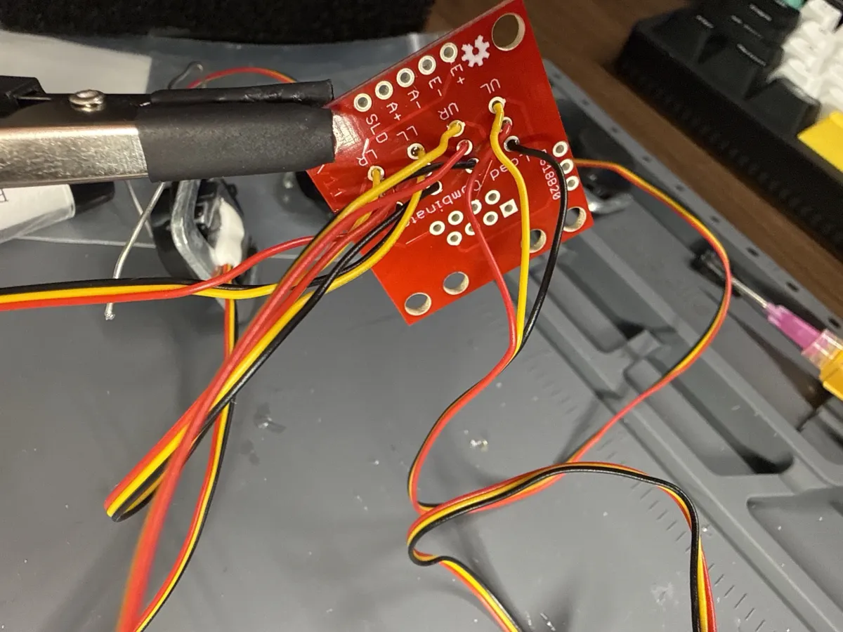
Combinator to HX711
I went through my old parts box from college for hookup wire, strippers, test leads and a breadboard with binding posts.
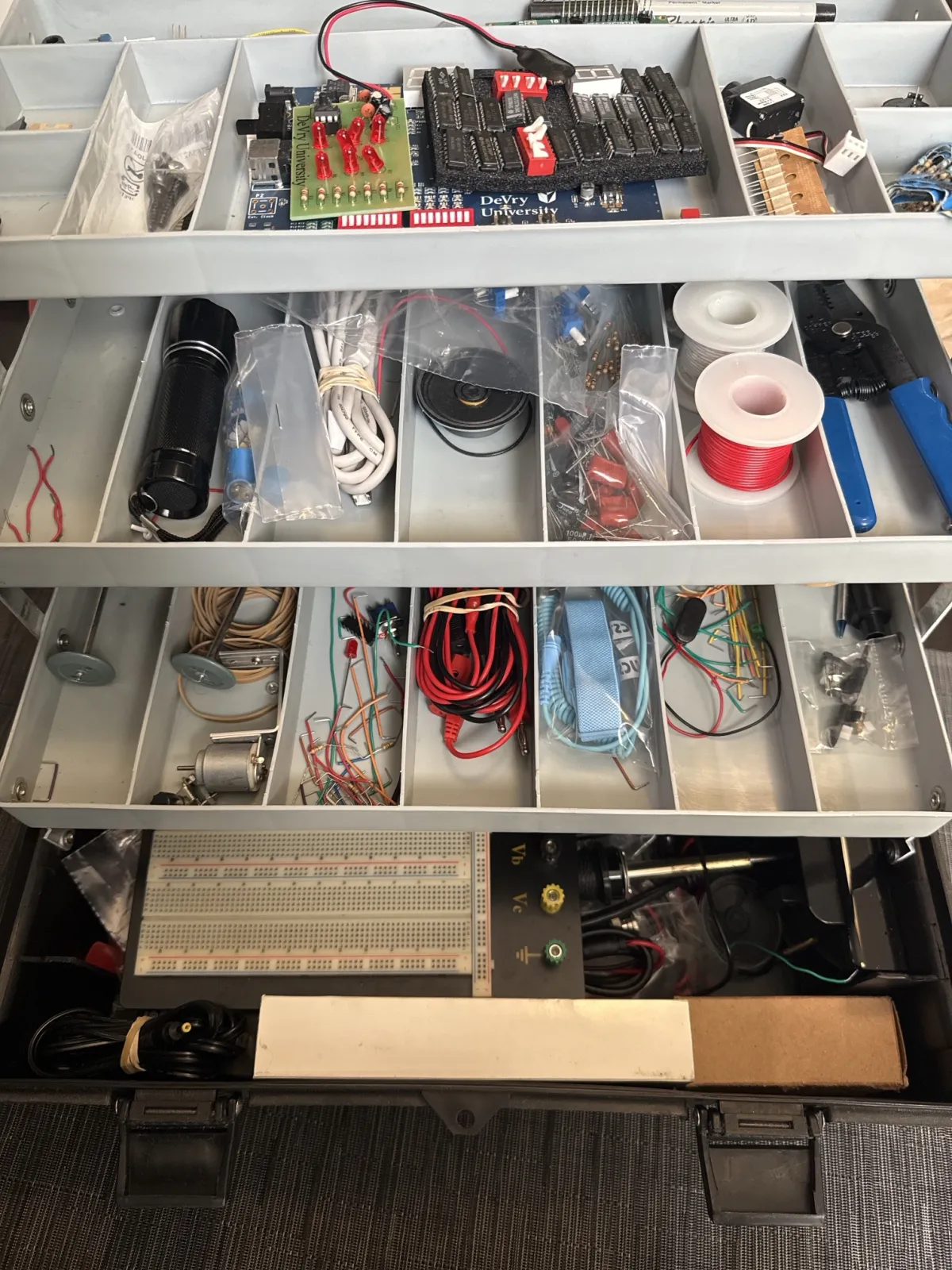
I didn’t have headers or female jumpers on hand, so I soldered hookup wire straight into the Combinator’s output holes. The magnifier helped. YLW is the shield wire and stays empty for the desk test.
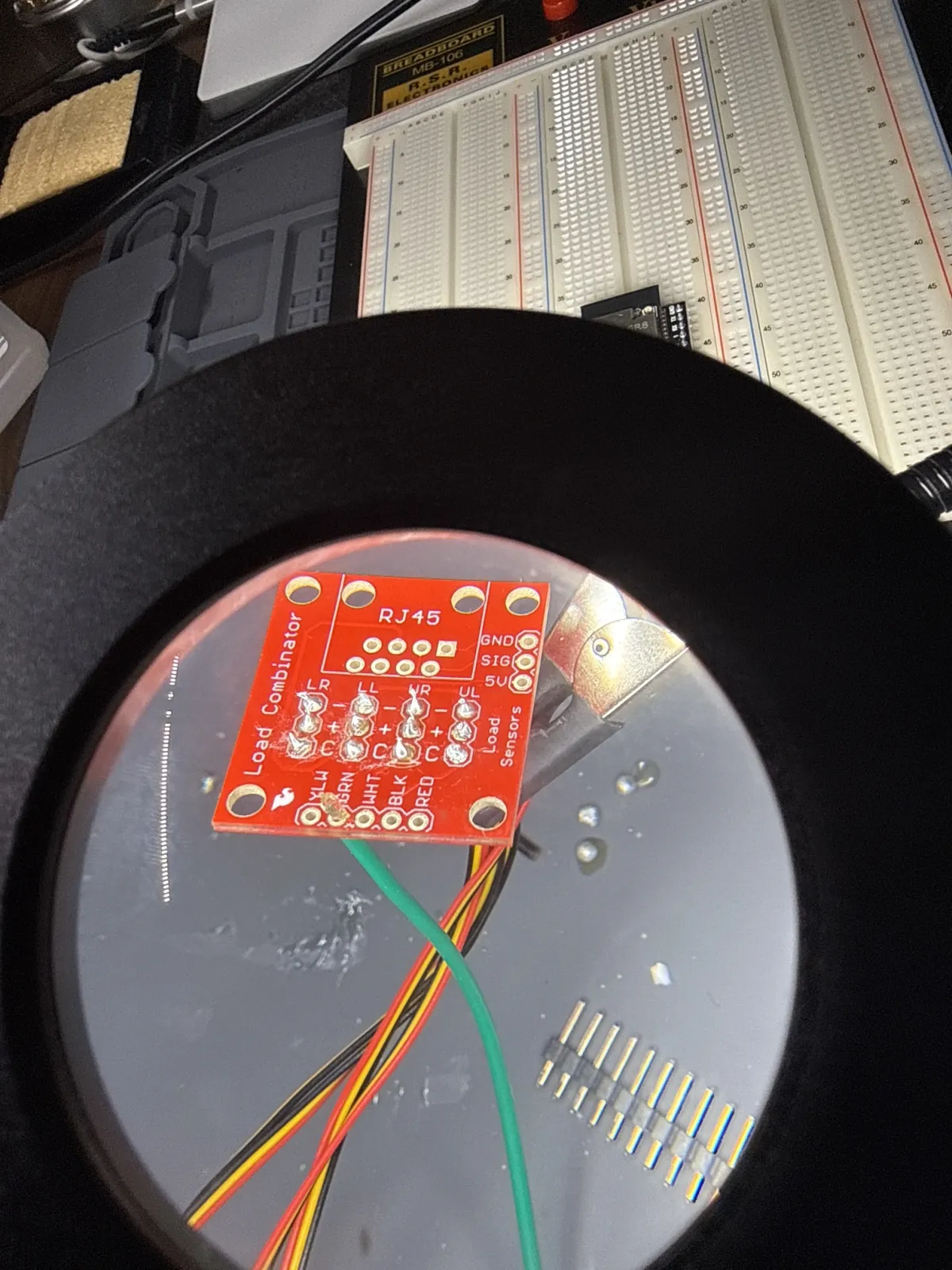
The other ends go into the HX711’s top row of screw terminals: red → E+, black → E−, white → A−, green → A+.
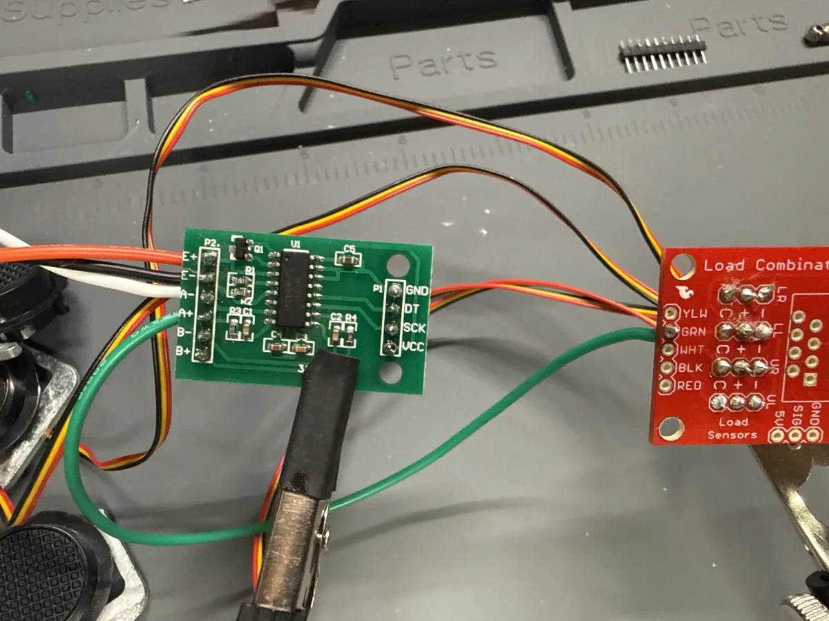
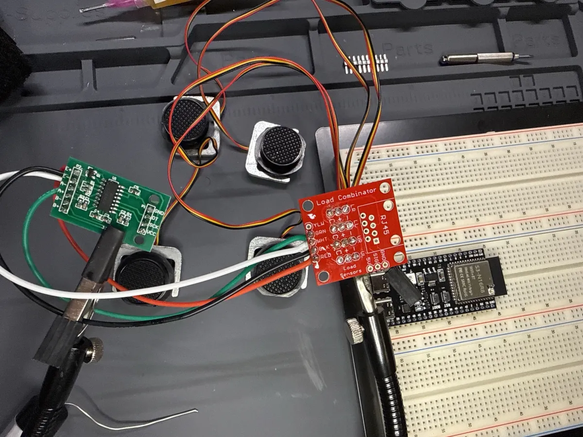
Checking the bridge
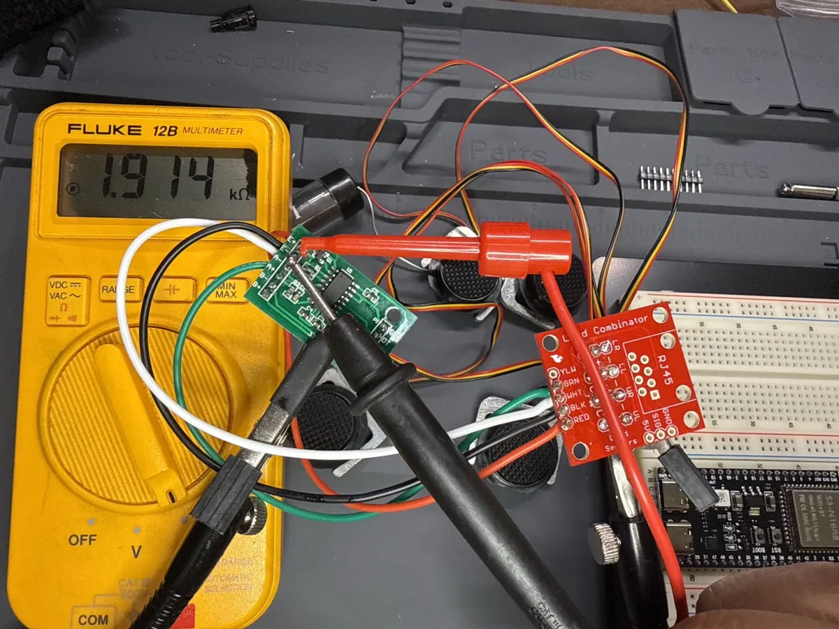
Before adding power, I measured the bridge at the HX711’s terminals.
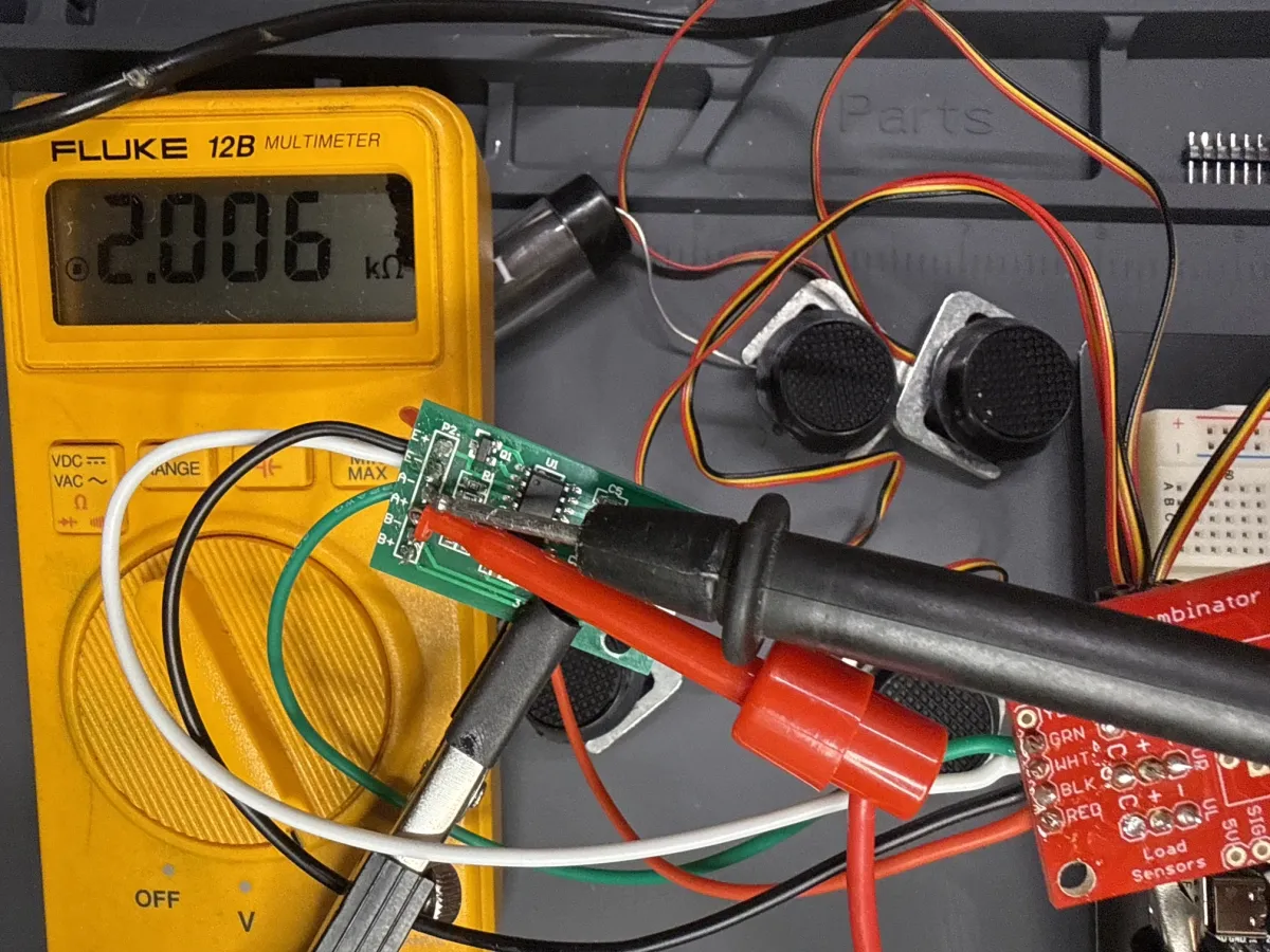
My multimeter is a Fluke 12B that Mr Ruiz, my instructor at Army AIT, gifted me about 15 years ago. Thanks, Mr Ruiz.
My first E+ to E− reading was 0.5 Ω, which looked like a short. Measured again right at the HX711’s pins, it read 1.914 kΩ. A+ to A− read 2.006 kΩ. Both are close to the ~2 kΩ I expected, so the bridge checks out.
ESP32-S3
The ESP32-S3 (N16R8) sits across the breadboard. I cut four solid jumpers: 3V3, GND, GPIO4 for DT and GPIO5 for SCK.
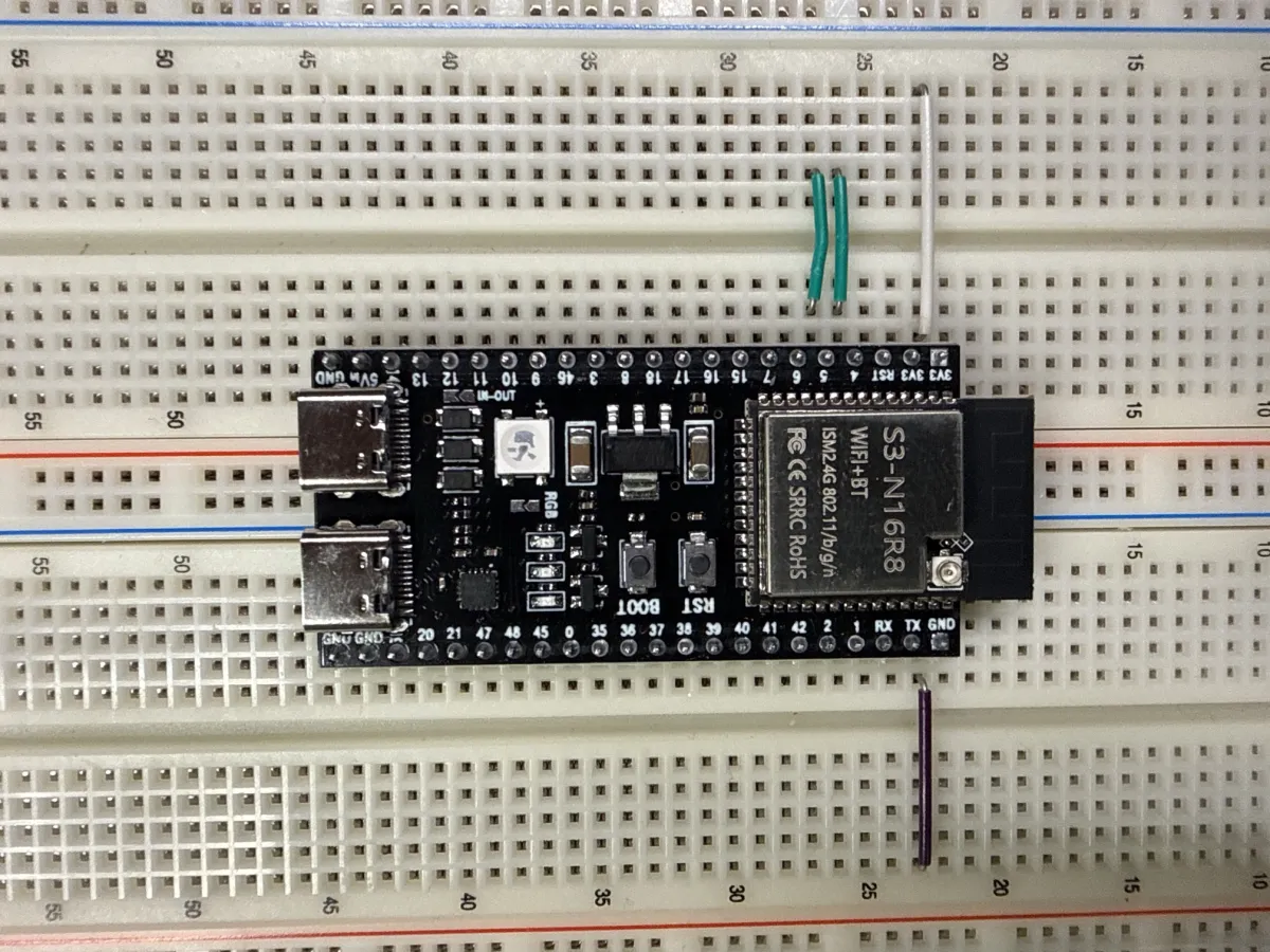
The HX711’s bottom row connects to those jumpers: VCC → 3V3, GND → GND, DT → GPIO4, SCK → GPIO5.
First flash
The board has two USB-C ports with no labels. One is the ESP32-S3’s native USB, which was still running the seller’s demo firmware. The other goes through a WCH CH343 USB-to-serial chip, and that’s the one the console needs.
After flashing, status reported −612,107 counts, stable, with 0 dropped samples. The number is raw and uncalibrated, so the sign and size don’t mean anything yet. For now I only need it to stay steady and change when I press a cell.
First press
My first 20-second recording looked like noise. The cells were loose on the mat and I was moving wires around. In a second run I kept my hands off the wires. At rest the reading stayed near −614,500, moving only tens of counts. Pressing UL dropped it by 100,000 to 200,000 counts. The raw data is in first-press.csv.
Press test
To check every corner, I had Claude write a short Python script. It asks me to press UL, UR, LL and LR in turn, records 3 seconds for each, and prints the lowest and highest raw count. It starts and ends with a hands-off reading.
› python3 tools/press-test.py
Hands off, then hit Enter...
  hands off: -614274 to -614060  (range 214)

Press and hold UL, then hit Enter...
  UL: -711531 to -666484  (range 45047)

Press and hold UR, then hit Enter...
  UR: -676807 to -661826  (range 14981)

Press and hold LL, then hit Enter...
  LL: -773464 to -669755  (range 103709)

Press and hold LR, then hit Enter...
  LR: -742921 to -666299  (range 76622)

Hands off, then hit Enter...
  hands off: -614177 to -613997  (range 180)
Every cell pushes the count more negative, so none of them is wired backwards. The ranges differ because I pressed each cell by hand with different force. Hands off, the range is about 200 counts before and after, and the reading returns to the same baseline.
Next
- Mount the cells on plates and cups, which means a trip to the hardware store.
- Calibrate with a known weight once they’re mounted.
- Until then, run
test noisehands-off to see how quiet the rig is over a longer stretch.
The step-by-step desk test guide is in the repo: docs/desk-test.md. The wiring for the finished pads is in docs/wiring.md.