Pit-pyro: the screen test
The screen was the last part I had not seen working. It now shows what the thermal sensor sees, with the hottest, average and coldest temperatures next to it.
After the test fit, the screen was the one part I hadn’t seen working. The firmware could detect it but didn’t draw anything on it yet.
On the desk
The screen is a 0.96” OLED, 128 × 64 pixels. It plugs into the Feather’s first STEMMA QT socket with a short cable.
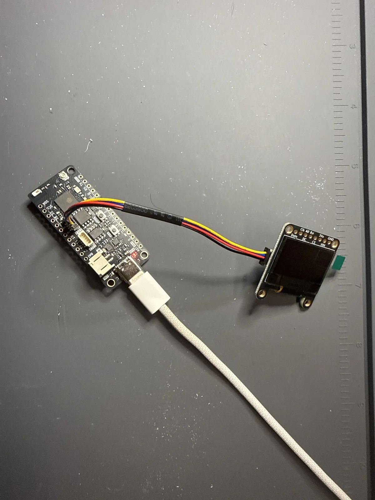
My Mac didn’t see the Feather at all. I tried another cable, another port, flipping the plug and resetting the board. Great troubleshooting, except I was plugging it into my work laptop. There are two Macs on the same desk, and I’m a goofball.
Turns out it helps to plug it into the right computer. It connected straight away, and the firmware found the screen at address 0x3D.
What it shows
The plan was a test pattern, but I wanted to see the sensor’s readings on it instead. The firmware now draws three things: a line around the edge of the panel, the sensor’s image, and the hottest, average and coldest temperatures in it (H, A and L).
Like on day one, the first image I took was of myself.
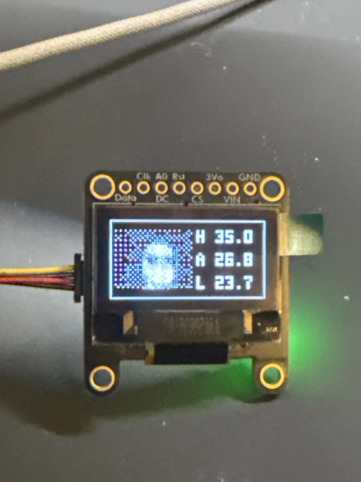
The sensor doesn’t take a picture. It reports 768 temperatures, 32 across and 24 down. Each one becomes a 2 × 2 block on the screen. The screen’s pixels are only on or off, so warmer blocks get more lit dots and colder ones get fewer. The brightness is scaled between each image’s own coldest and hottest reading. It updates about twice a second.
The line around the edge is for checking how the lit area sits in the enclosure’s window.
As a kid I used to read Popular Mechanics even though I couldn’t understand it, and I dreamed of building my own stuff like this. It’s crazy that we can do this now. I would have never been able to do this without AI.
Next
- Check the screen in the enclosure’s window.
- Firmware for the trigger, the menu button, the buzzer and the laser.
- A camera mode in the menu, so I can show people at autocross what the sensor sees.
The code is in PR #12.