Pit-pyro: test-fitting the enclosure
A friend printed the first full enclosure. I fitted every part into it, broke the menu button holder, and fixed five things in the model.
A friend printed the first full enclosure for pit-pyro, the v0.4 design from measuring the real parts, and pressed in the five brass inserts. Shoutout to Spencer! This is the test fit: I put every part in, and whatever didn’t fit got fixed in the model.
What fit
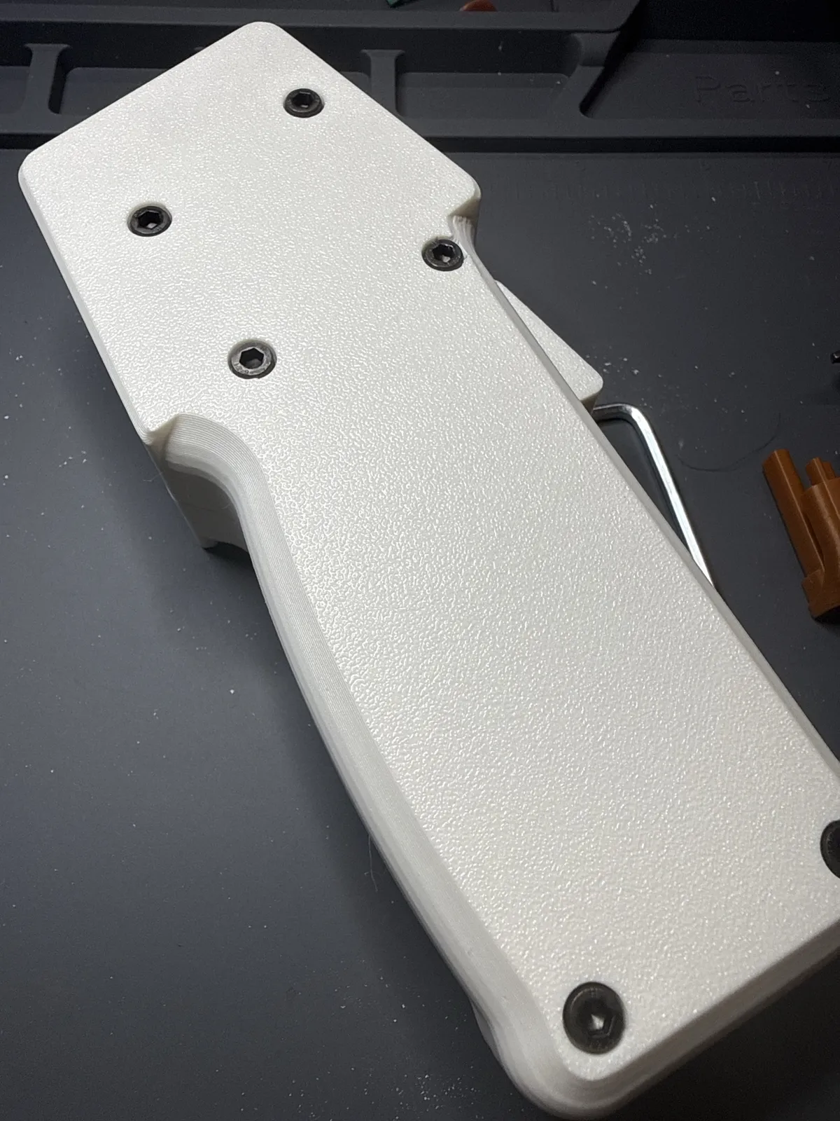
The halves didn’t close at first, so I filed around the inserts. After that they closed with a thin, even seam.
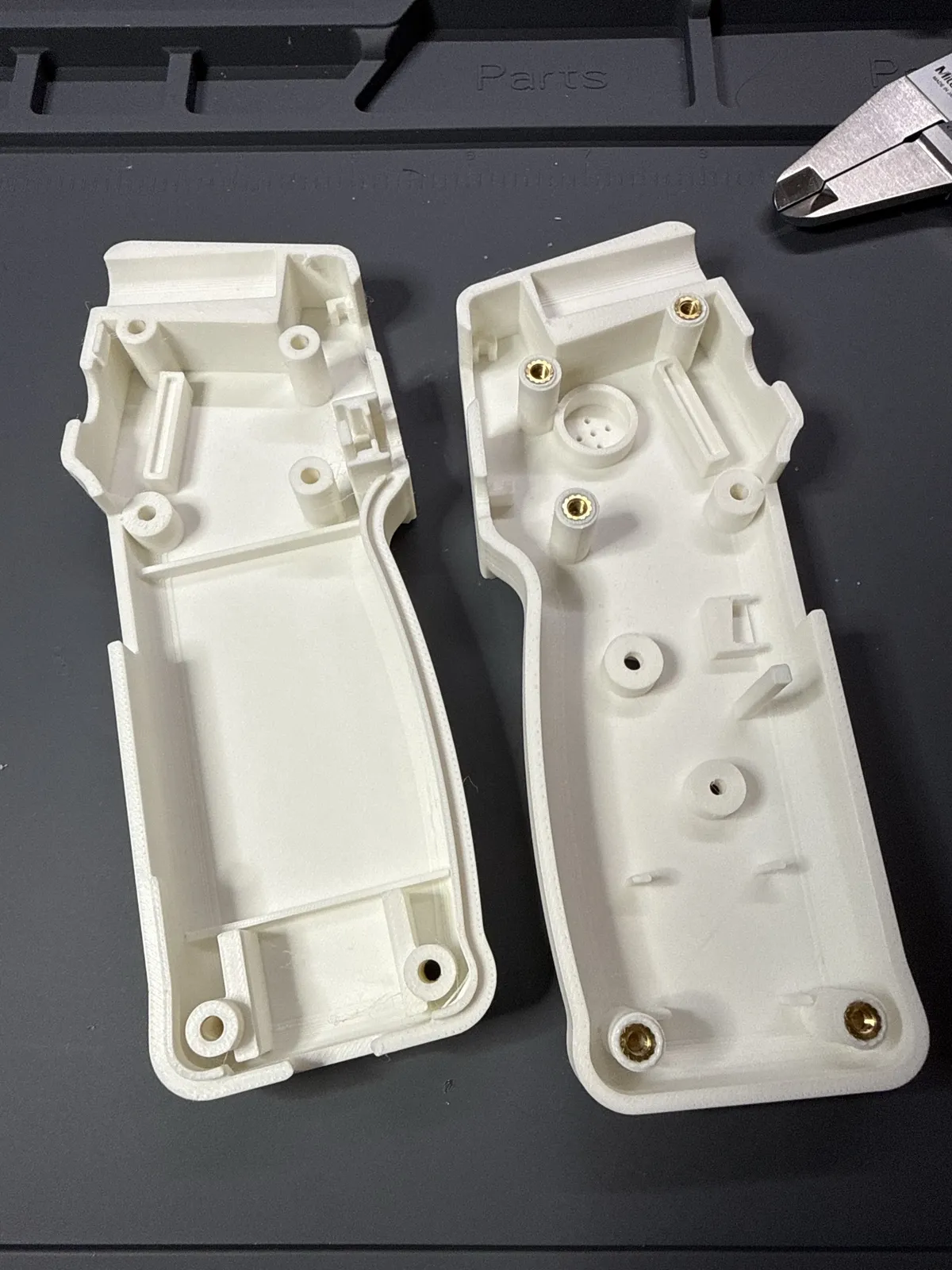
The Feather sits in its rails with the USB-C port square in its opening. The battery, the clock, the buzzer and the screen went into their places with no changes.
The menu button
The button didn’t fit between the case wall and the bar behind it. I forced it, and the bar broke off.
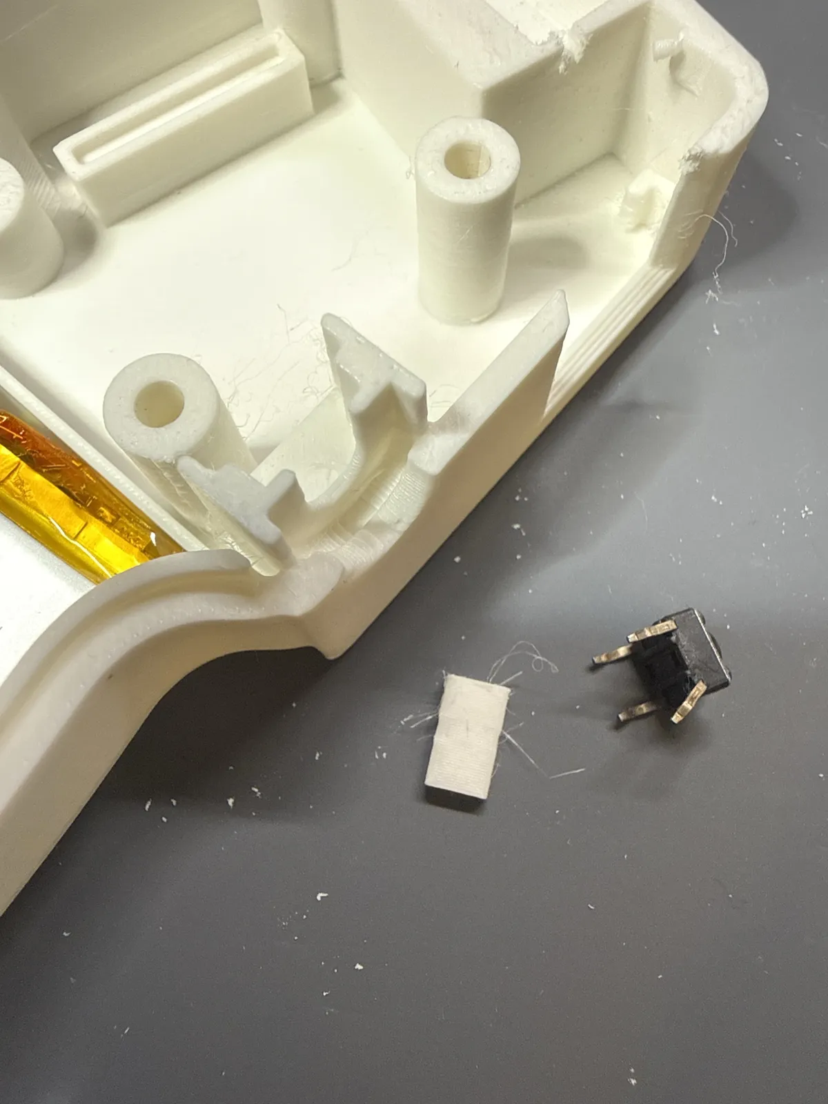
When I measured the parts I wrote down 2.70 mm for the button’s body. I measured it again and it’s 3.6 mm, so the 3.0 mm slot was too short. The plunger also stands only 0.45 mm above the body, not the 1.5 mm in the model, so the cap never reached it.
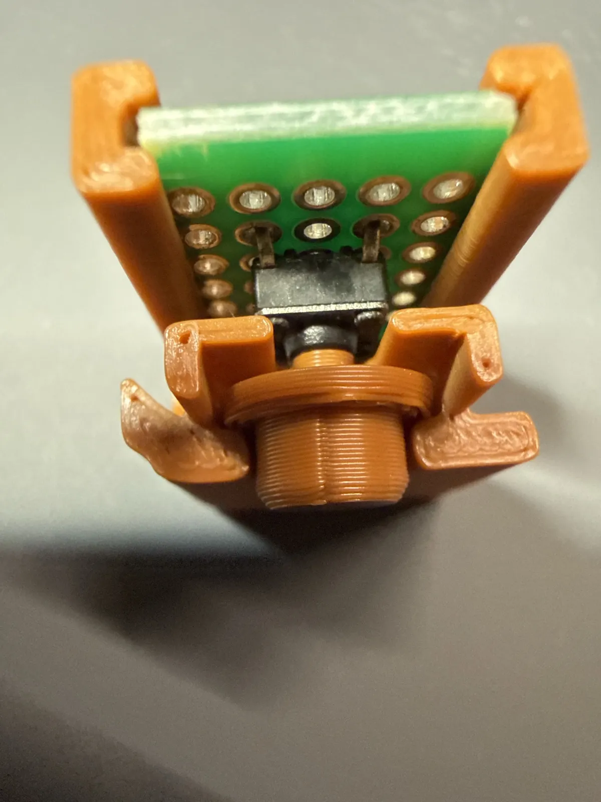
The bar was too weak anyway, and I didn’t like any version of it. The button is now soldered to a 13.45 × 20 mm piece of perfboard that slides into two rails, the same way the sensor is held. The cap got a small nub that reaches the plunger.
I didn’t want to reprint the whole case to try it, so there’s a new test print with just that corner. I printed it at the library on a Prusa MK4. The fit is perfect: the board slides into the rails and the button clicks.
The trigger
The trigger didn’t spring back. The stop below it wrapped around the trigger’s ear with no clearance, and the ear got stuck in it. I filed the ear’s edges. In the model the stop is now shorter than the ear, so it can’t wrap around it.
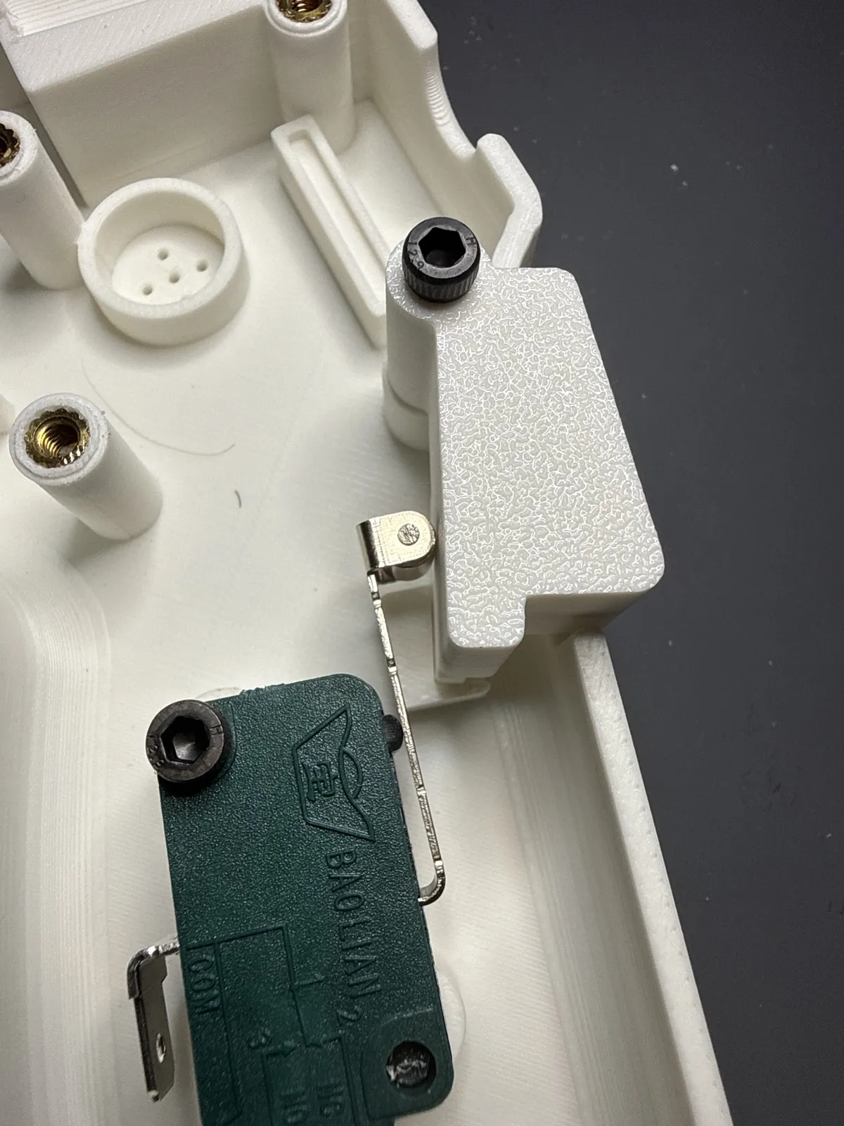
The M3 × 30 hinge screw didn’t reach its nut. By the model’s own numbers it only went 0.7 mm into the nut, about one thread, with the halves fully closed. I put the nut on a spare screw and pushed it about 2 mm deeper into the plastic with the soldering iron at 220 °C. The screw reaches it now.
It was the only screw that was too short. In the model its nut pocket went from 2.6 to 4.5 mm deep. The depth of each nut pocket now comes from the length of its screw, and the model gives an error if any screw has less than 2 mm of thread.
The laser and the sensor
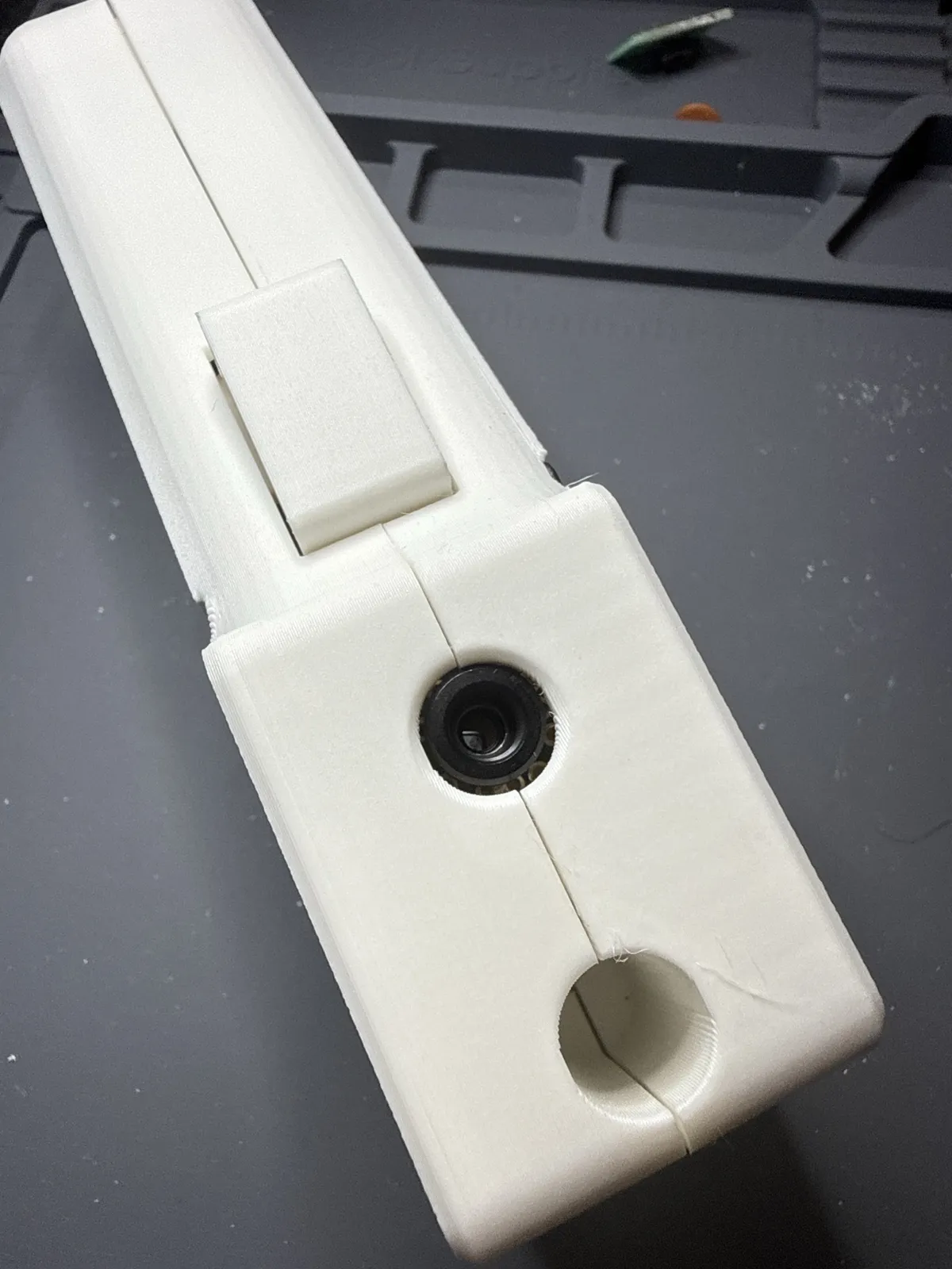
The laser’s two wires come straight out of its back end, and the model had no way out for them. I filed a notch for this print and added a 5 mm channel to the model.
The sensor in this build is the perfboard one from day two. The one on the custom board sits tilted, so it’s the spare for now.
Each half held the sensor’s board by one edge, so the board tipped over every time I tried to close the case. Blu Tack held it for this print. In the model the rails now run along the board’s top and bottom edges, so it stands on its own in one half.
Closing it
With the hand fixes, every part is in and the case closes with its five M3 × 20 screws. It’s surprisingly sturdy, and the trigger clicks the switch and springs back.
Next
- Reprint the halves, the button cap and the trigger, and check each fix in plastic.
The screen was the last part to test. That’s in the screen test.
The fixes are in PR #11, and the model is enclosure.scad.