Pit-pyro: building the sensor board
The custom circuit boards for the thermal sensor arrived. I built one and read frames from it on the Feather.
On day two I designed a small circuit board to replace the hand-cut perfboard under pit-pyro’s MLX90640 sensor. The boards arrived today, along with the extra sensors, so I built one.
The board
The board is 20 mm across. The sensor goes on the front. The back has the two pull-up resistors, the two capacitors and four holes for the cable, labeled with the wire colors.
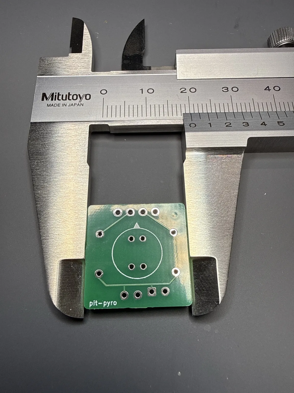
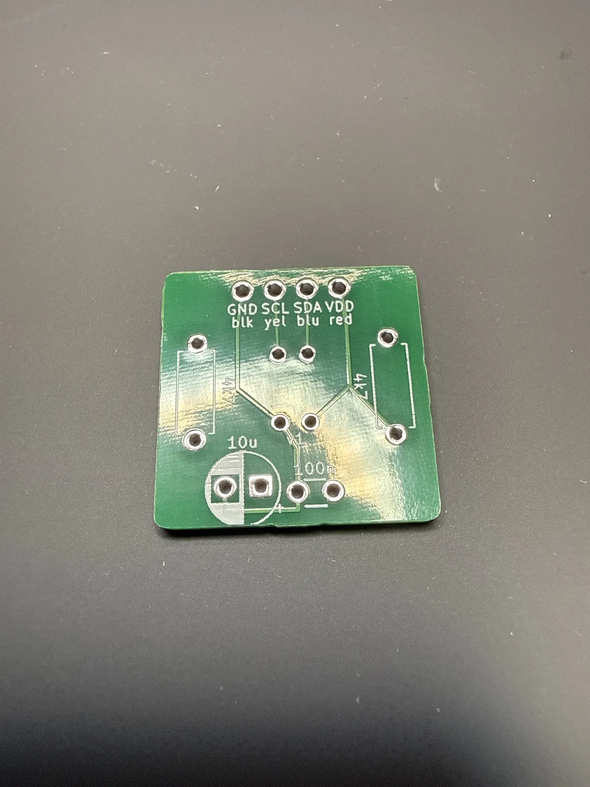
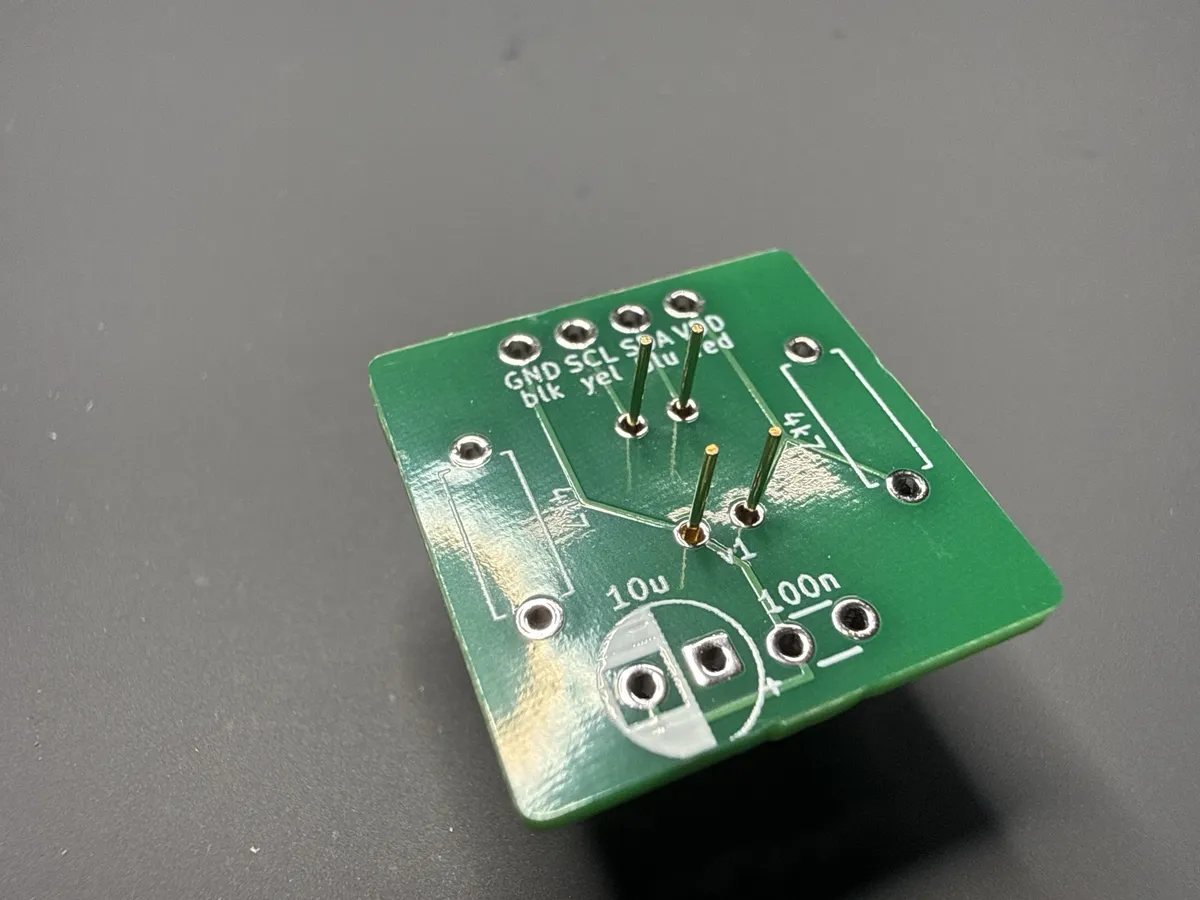
The sensor dropped in from the front and all four legs came straight through their holes. It dry fits like a glove.
Building it
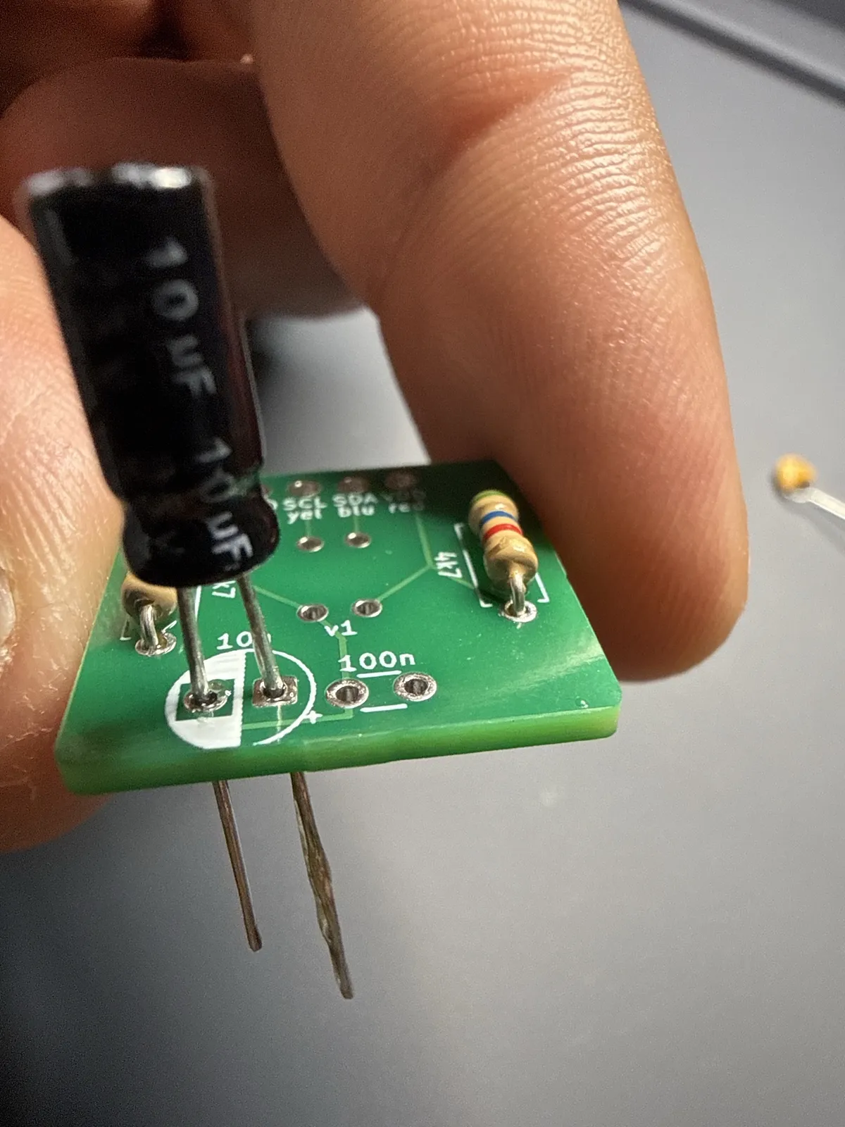
I only had one 4.7 kΩ resistor left, so the second pull-up is 5.6 kΩ. Soldering on this board is much easier than on the perfboard.
The 10 µF capacitor stands 13.2 mm off the board, and the pocket behind the board in the head is 10 mm deep. I forgot to check its height when designing the board. For now it’s soldered standing, with some leg showing so it can be folded over later.
I soldered the sensor in without pressing it flush, so it sits slightly tilted. I’ll reseat it with solder wick.
Wired and tested
The cable is a 150 mm STEMMA QT cable with the header pins cut off one end, soldered through the labeled holes.
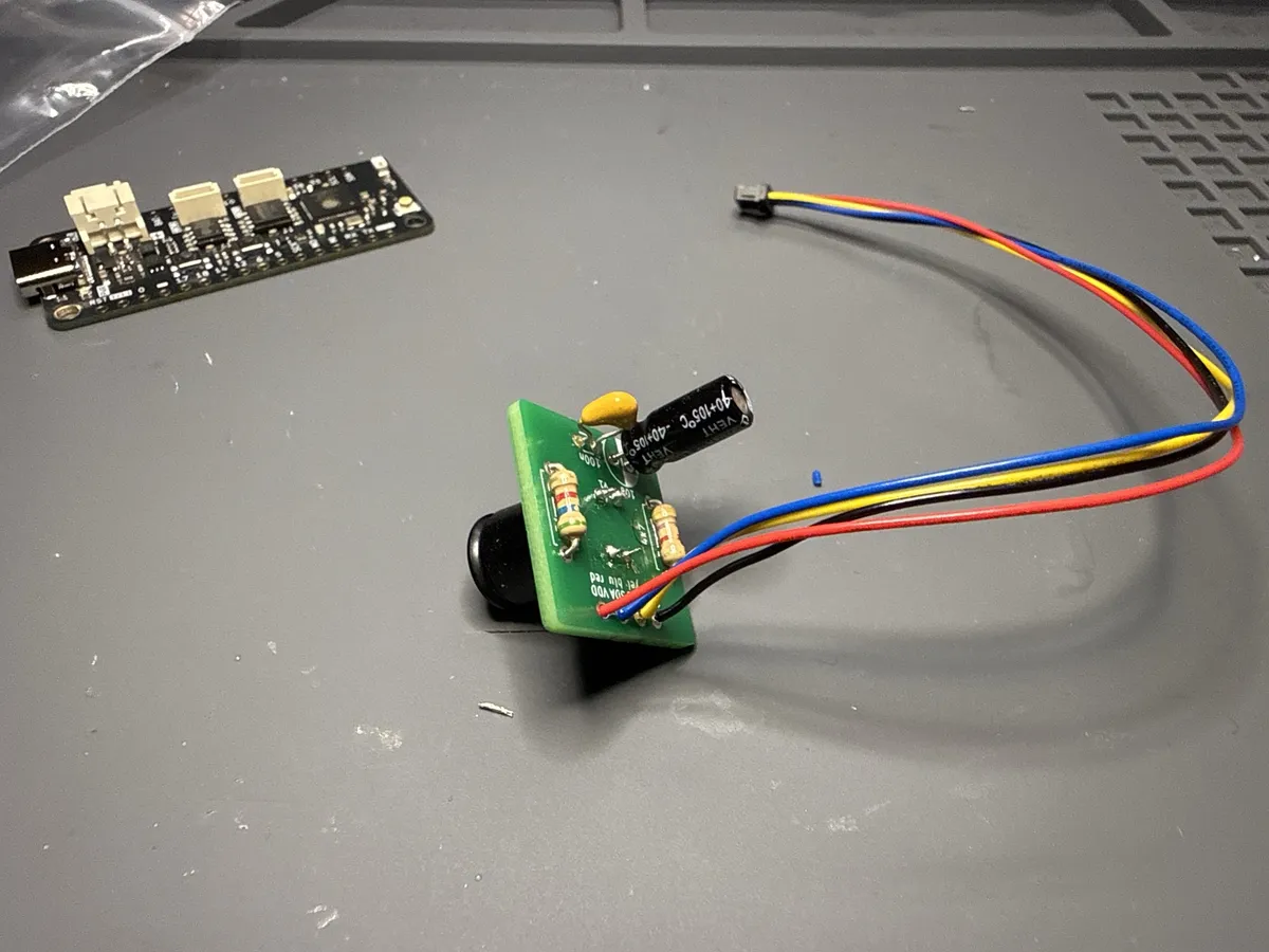
The meter showed no shorts between the wires, and both pull-ups read their values. The Feather needed a reflash before it would show up over USB. After that the firmware found the sensor at address 0x33 with no bad pixels.
I aimed it at a flat wall and saved three frames. They averaged about 26 °C, with a pixel spread of 0.36 °C. There are no stripes like on day one. There is a faint pattern every four columns, about 0.3 °C, that the perfboard sensor from day two didn’t show.
The design files are in hardware/sensor-carrier.
Next
The sensor has had enough attention for now. Next are desk tests for the parts I haven’t tried yet:
- The 0.96” OLED screen.
- The DS3231 clock.
- The LiPo battery.
- The trigger switch.
- The menu button.
- The aiming laser.
- The buzzer.