Pit-pyro: the desk test, day two
A third sensor, this time with the capacitors I skipped on day one. The stripes are gone, and the sensor is getting its own small circuit board.
On day one I got the first thermal image out of pit-pyro’s sensor, an MLX90640, but every fourth column read about 1 °C high. I also skipped the two capacitors the plan called for across the sensor’s power pins, because soldering them onto the legs with everything else seemed impossible. Day two was a third sensor, built properly.
Capacitors
Melexis, the sensor’s maker, recommends a 100 nF and a 1 µF capacitor close to the power pins to keep the supply clean. I used a 100 nF ceramic and a 10 µF electrolytic I had on hand. The 100 nF catches fast spikes and the 10 µF covers slower dips. I soldered the two together first, then onto the sensor’s power and ground legs, with short leads.
A clean board this time
On day one the perfboard’s pads wouldn’t take solder. This time I sanded the pads with 2000 grit until they were shiny and cleaned them with isopropyl alcohol. All four legs soldered cleanly, with no bridges.
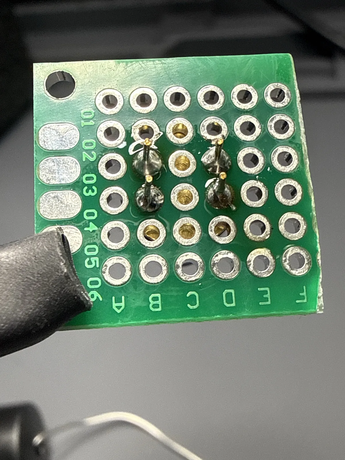
The same multimeter check as day one confirmed power and ground: 0.667 V from ground to a data wire and 1.318 V from power, the same pattern as the second sensor.
Then the capacitors, the two pull-up resistors and the four cable wires went on. With everything piled onto the legs it’s messy, but this sensor is only for the desk.
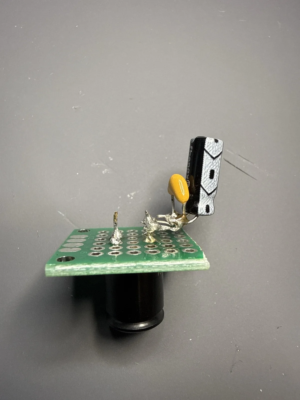
The stripes are gone
The datasheet says to let the sensor warm up for about 4 minutes before trusting the temperatures, so the viewer now shows how long it’s been running and says “settling” until then.
After the warm-up I aimed it at the same kind of flat surface as on day one. Every fourth column is now within ±0.13 °C, which is noise. On day one it was 0.7 to 1.2 °C high. The overall spread halved too, from about 0.8 °C to 0.4 °C.
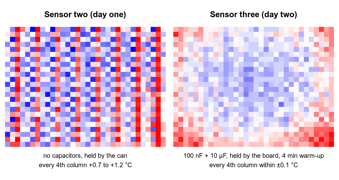
Three things changed at once: the capacitors, holding the sensor by its board instead of its metal body, and the warm-up. I can’t say which one fixed it, but the missing capacitors are the most likely.
The sensor also reported one bad pixel, which the factory flags in its memory. That was the first real use of the firmware’s bad-pixel correction.
A circuit board for the sensor
Perfboard was never going to be good enough for the final build, and ready-made boards for this sensor are sold out. So I’m having a 20 × 20 mm board made for it, laid out in KiCad. The sensor goes on the front. The back has the two pull-up resistors, both capacitors, and four holes for the cable, labeled with the wire colors.
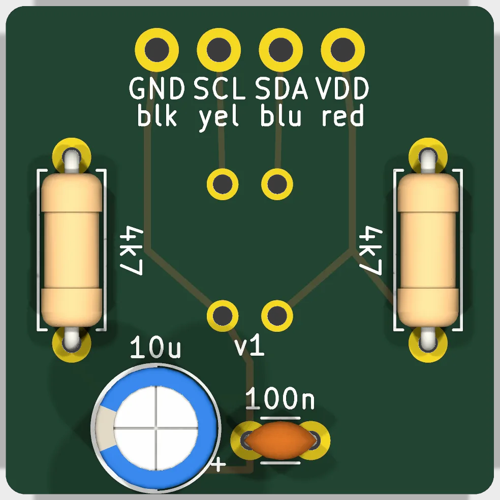
The design files are in hardware/sensor-carrier.
Next
- Build the first prototype with the new sensor board and all the parts.
- Work out the outer, middle and inner temperatures, and check them against a cooking thermometer in a cup of hot water.