Pit-pyro: the desk test, day one
Before the enclosure, the electronics get tested on the desk. Day one was the thermal camera: one sensor lost, a second one wired straight to its legs, and the first thermal image.
Pit-pyro is a handheld tire pyrometer. Before anything goes into its enclosure, I’m testing the electronics on the desk, the same way I did for corner-scales. Day one was the thermal camera, an MLX90640 (“the sensor” below).
The plan
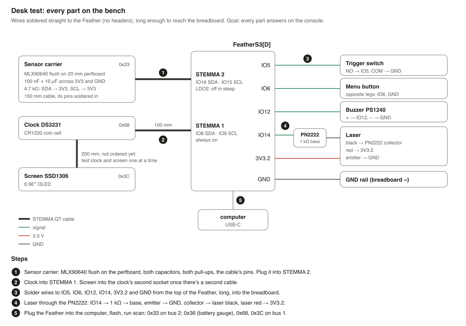
The Feather has two STEMMA QT sockets, small plugs for connecting sensors. Each one is its own I2C bus, the two-wire data connection the sensor uses. The sensor gets one socket to itself, and the clock and screen share the other. I2C needs a pull-up resistor on each data wire, and neither the sensor nor that socket has them, so I’m adding two 4.7 kΩ resistors to 3.3 V.
The Feather has no headers. In the grip it sits flat against the battery with wires soldered on top, so I’ll solder the final wires straight to the pins I use.
The first sensor
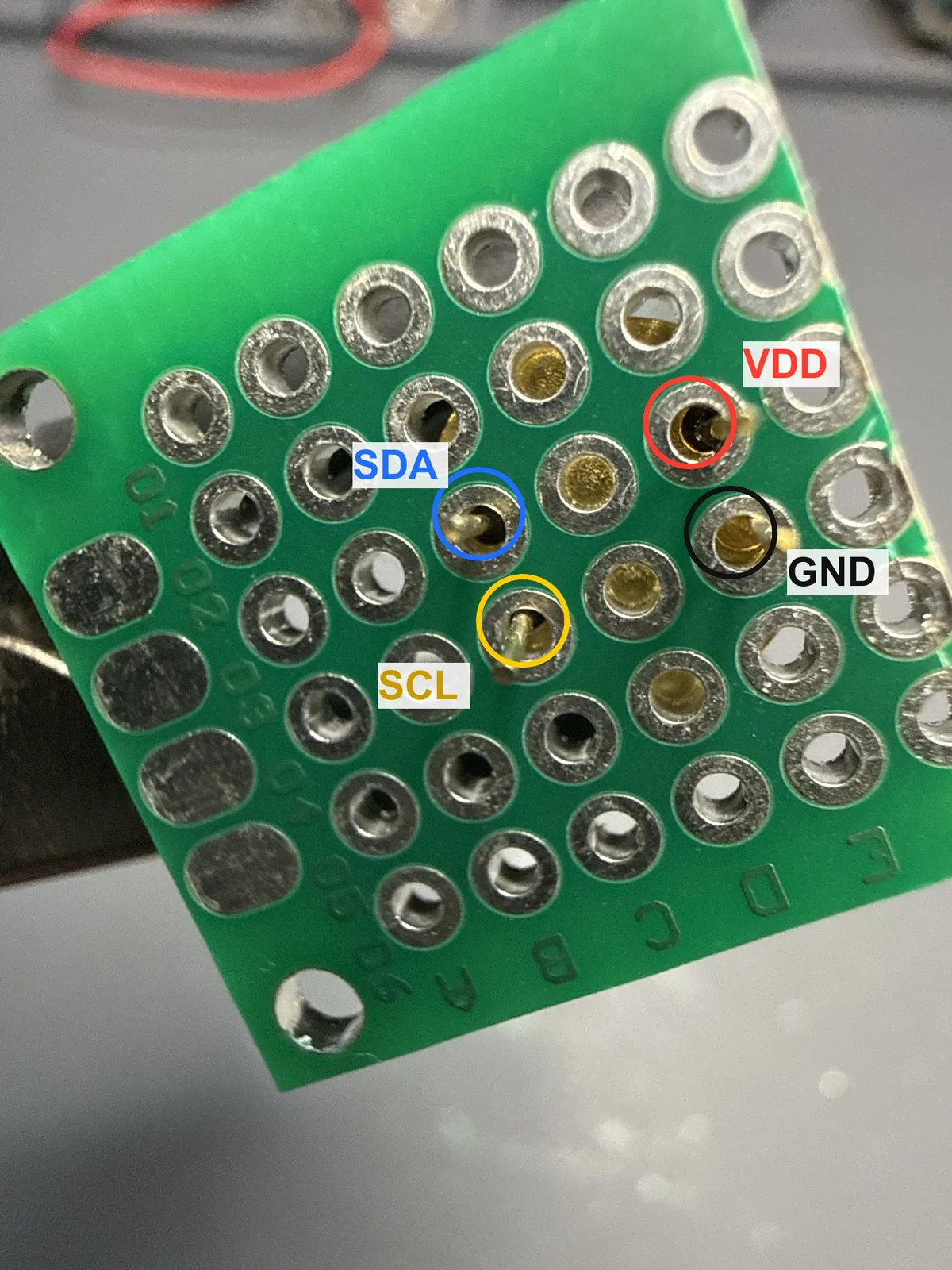
The sensor sits on a 20 mm square of perfboard, which slides into rails in the enclosure. I cut it from a strip with a knife: 20.00 × 19.90 mm.
I set the sensor with its tab toward the perfboard’s four pads, where the cable connects. Seen from below, that puts the two data legs (SDA and SCL) nearest the pads, and power (VDD) and ground (GND) on the far side.
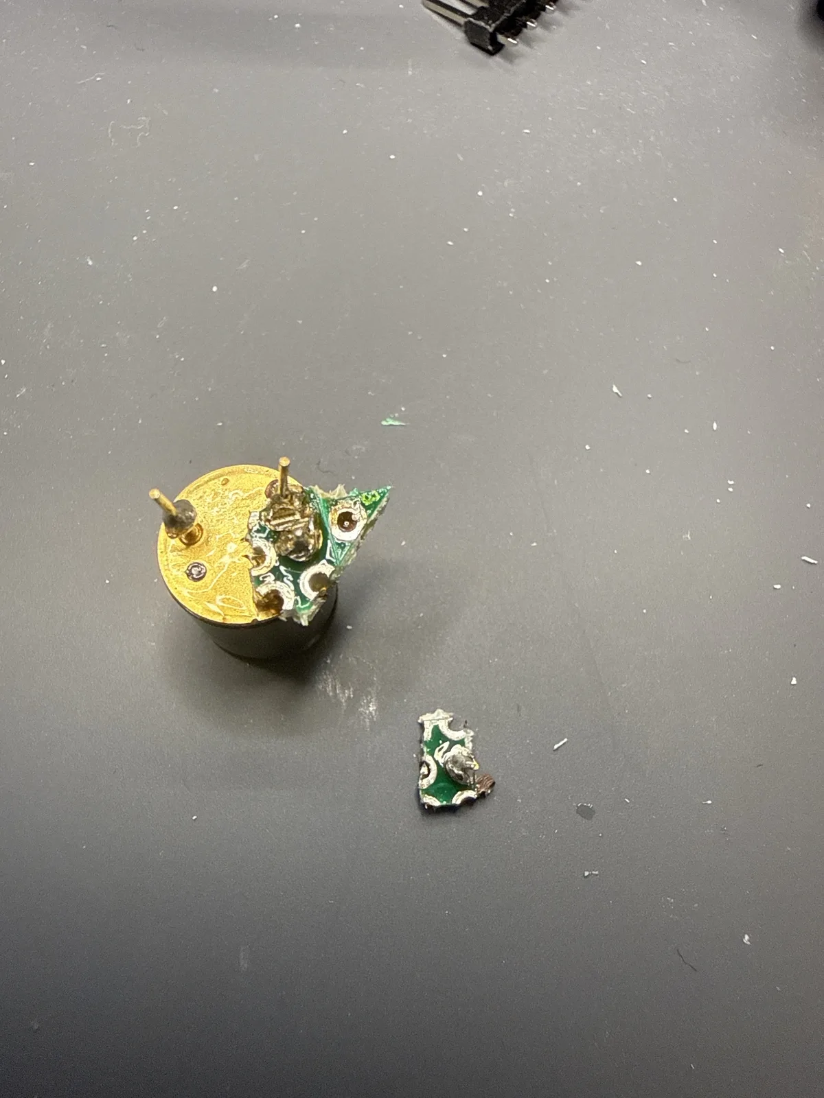
The two data legs sit in neighboring holes, and my solder ran them together into one blob. I couldn’t clear it with a solder sucker, so I cut the perfboard apart around the legs to get the sensor out. One leg snapped off flush with the base. I set that sensor aside and used a spare.
The second sensor
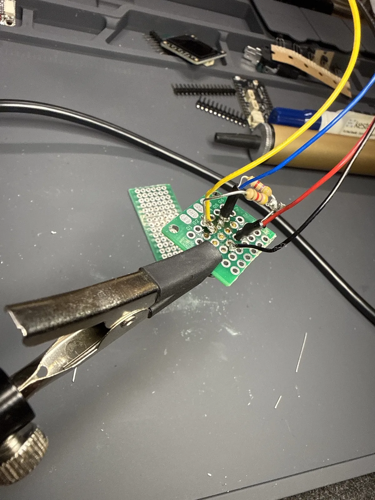
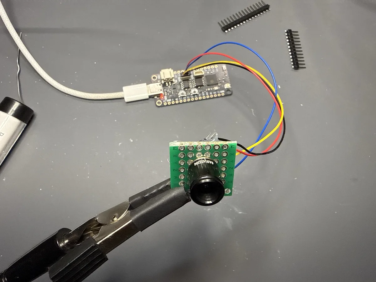
The perfboard’s pads wouldn’t take solder, even with flux at 355 °C. So the perfboard only holds the sensor now. I cut the pins off the end of a STEMMA QT cable and soldered its four wires straight onto the sensor’s legs.
Swapping power and ground would kill the sensor, so before plugging it in I checked the wires with the multimeter’s diode setting, which shows the voltage across a diode. From the black wire to a data wire it read 0.665 V, one diode, and from the red wire 1.324 V. Swapped wires would flip those two readings, so black is ground and red is power.
The two pull-up resistors went on at the base of the legs, and hot glue holds it all together.
The glue stands about 12 mm off the back of the perfboard, and the enclosure reserves 10 mm there. That’s only a keep-out zone in the fit check, not a cut, so the shell fits 12 mm as long as the glue stays 1 mm in from the edges. I’ll squeeze it in.
Next time I’ll skip the perfboard: glue the sensor to a plain plate and solder wires to the legs, or use female header sockets. I also really need to sharpen my soldering.
First frames
I had Claude write a quick check program to read the sensor. Every frame came through. The raw numbers showed a warm shape in one corner, probably the lamp on my magnifier.
The real firmware is in Rust. Turning the sensor’s raw data into temperatures takes the calibration math from Melexis, the sensor’s maker, which is now ported to Rust. I checked it against Melexis’s own C code on the same data, and they agree within 0.00007 °C on all 768 pixels.
Stripes
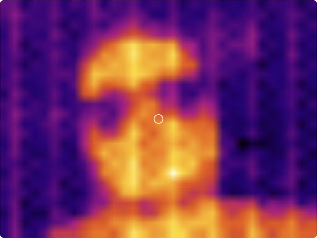
Every fourth column reads 0.7 to 1.2 °C high. It’s the same at 1, 2 and 4 images a second, and when I turned the sensor 90° the stripes turned with it, so they come from the sensor itself. The tire’s outer, middle and inner readings will each average about 10 columns, which cancels them out. It may be uneven heating, from the soldering or from the helping hand’s clip touching the side of the sensor.
Seeing it live
To see what the sensor sees, there’s now a viewer page that runs in Chrome. It reads the Feather over USB, and nothing leaves the computer. The first live image I took was of myself.
Next
- Add the 100 nF and 10 µF capacitors across the sensor’s power pins, then check whether the stripes change.
- Try a spare sensor on a glued plate with no perfboard, and compare the stripes.
- Let the sensor sit untouched for a few minutes, holding it by the perfboard instead of its metal body, and see if the stripes change.
- Wire up the rest: trigger, menu button, buzzer, laser, clock and screen.
- Work out the outer, middle and inner temperatures, and check the readings against a reference thermometer.
The firmware, the viewer and the desk test guide are in PR #4.