Pit-pyro: measuring the real parts
I measured every part with calipers before the first print. Two of them were much bigger than the model assumed, so I redesigned the enclosure around them.
The parts for pit-pyro arrived. Pit-pyro is a handheld tire pyrometer: a thermal camera reads a tire’s outer, middle and inner temps in one trigger pull, and an ESP32-S3 board (a FeatherS3[D], “the Feather” below) shows them on a small screen and logs them.
The enclosure is a two-half pistol grip in OpenSCAD. Version 0.3 was designed entirely from datasheets and store listings, so before the first print I measured every part with my Mitutoyo calipers (0.05 mm resolution) and updated the model.
The trigger switch
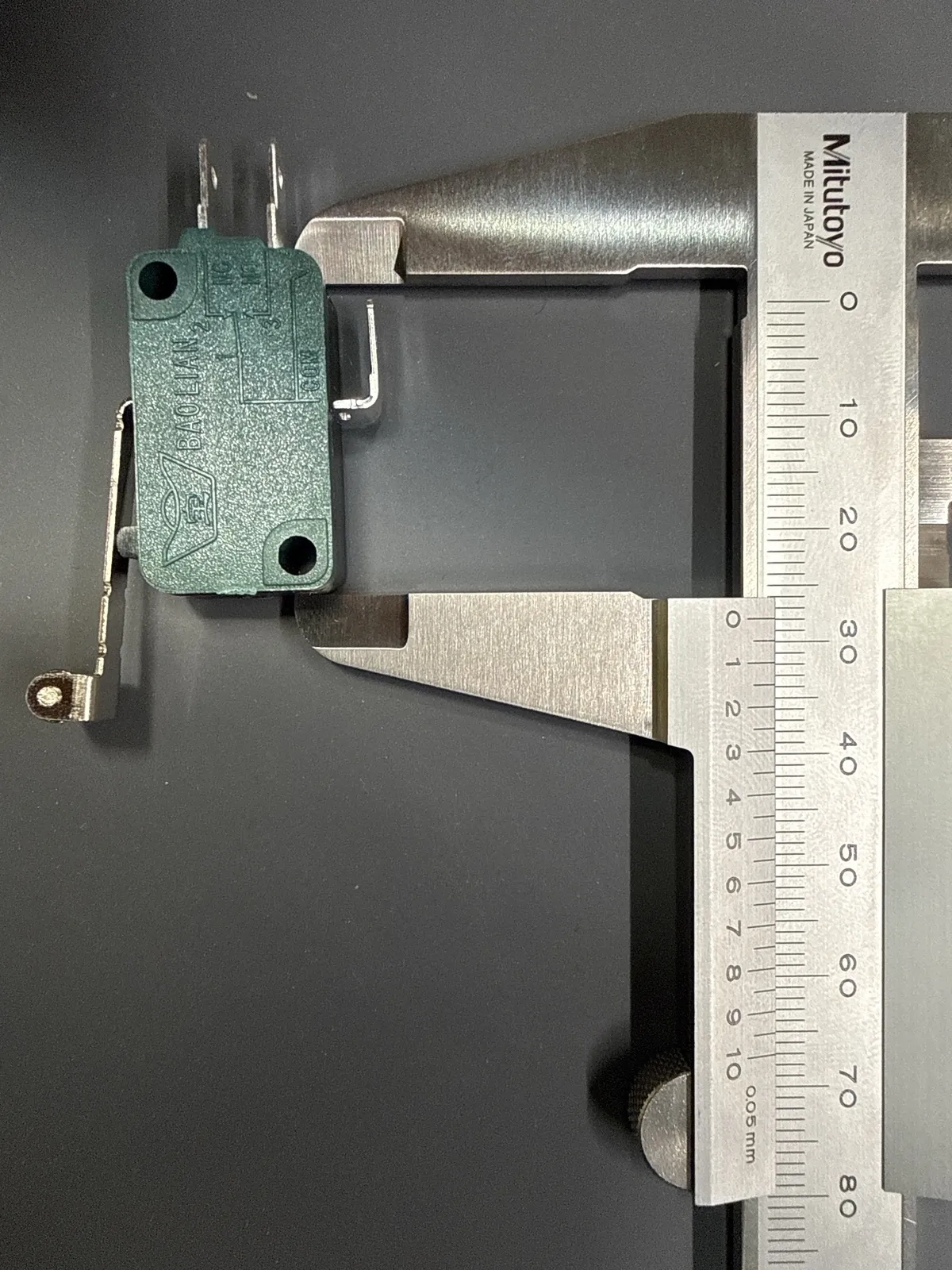
I started with the switch, since the trigger is designed around it.
The model assumed a small switch, 19.8 × 10.2 × 6.4 mm. The one I have is a standard-size switch, 28.00 × 15.95 × 9.85 mm, about 3.4 times the volume.
Its wheel sits on a long lever that reaches 8.25 mm past the body and stands 9.65 mm off it. The model assumed 5. My first reading caught the lever instead of the wheel.
The one thing that matched was the travel: 2.7 mm to the click, then 1.4 mm more before it bottoms out.
The laser
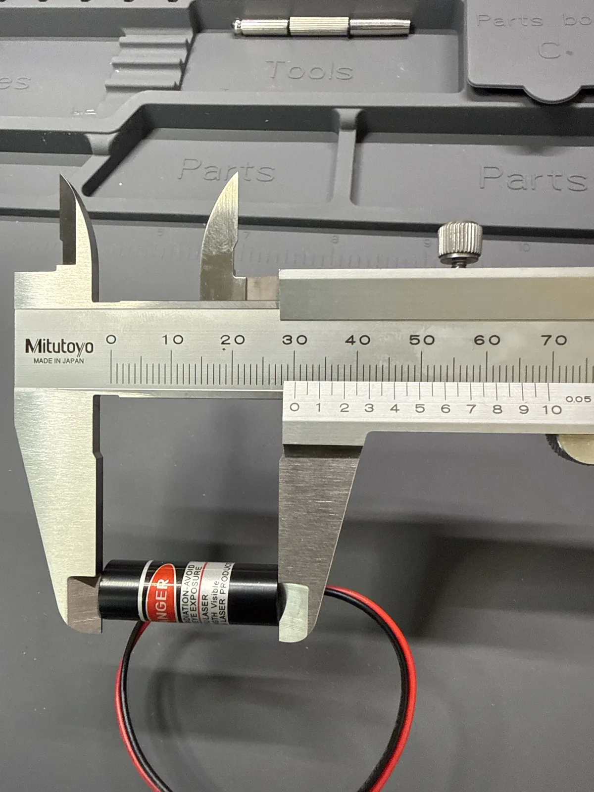
The laser was the other big difference. The model assumed Ø6 × 14 mm; the real laser is Ø10.10 × 30.25 mm, about 6 times the volume. It takes over half the length of the head and has to fit beside the thermal camera.
Everything else
- I added the menu button after ordering the parts, so I used one from my parts box. It’s 0.8 mm shorter than modeled.
- The Feather’s board is 1.1 mm thick, not the standard 1.6.
- The screen’s board is 5 mm longer than modeled.
- I misread the battery’s width as 29.65 mm at first. It’s 34.65, a little wider than modeled.
- The thermal camera’s lens sits 11.4 mm above the board, not 5. I misread its legs as 10 mm at first; they’re 6, so the camera has to sit flush on its perfboard to leave enough to solder.
- The clock and buzzer match.
| Part | Assumed (v0.3) | Measured |
|---|---|---|
| Trigger switch | 19.8 × 10.2 × 6.4 | 28.00 × 15.95 × 9.85 |
| Switch wheel, off the body | 5 | 9.65 |
| Laser | Ø6 × 14 | Ø10.10 × 30.25 |
| Menu button height | 3.5 | 2.70 |
| FeatherS3[D] | 52.3 × 22.9 × 1.6 | 51.40 × 22.90 × 1.10 |
| Screen board | 29.2 × 26.7 | 29.50 × 31.70 |
| Battery | 34 × 62 × 5 | 34.65 × 61.60 × 5.00 |
| Thermal camera | Ø9.2, lens 5 above the board | Ø9.40, lens 11.40 above |
| Clock | 25.4 × 17.8 × 8 | 25.85 × 17.75 × 7.95 |
| Buzzer | Ø12.2 × 7 | Ø11.80 × 6.55 |
All in mm. The full table is in the enclosure README.
Redesigning around the switch
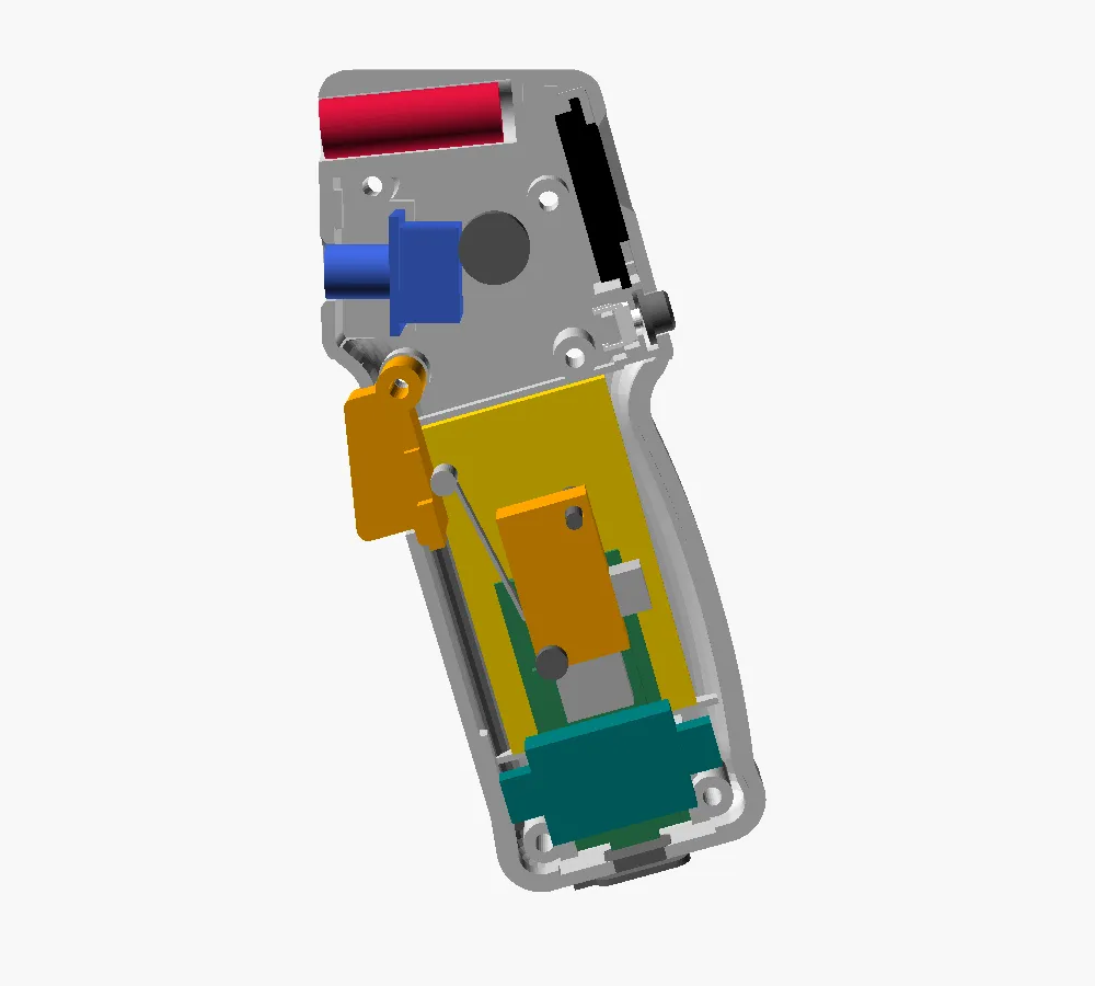
I dropped the measured parts into the old v0.3 design. Most parts only needed small changes: the laser’s holder needed two screw posts moved, and the thermal camera moved back. The switch didn’t fit. It ran into the Feather.
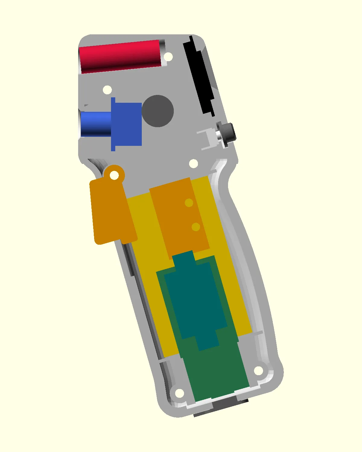
I kept the switch rather than wait on a smaller one. It now sits upside down beside the Feather, on two posts off the right wall.
A narrower trigger
The first layout kept the 18 mm trigger, but it passed within 0.5 mm of the battery. That’s too small, so I narrowed the trigger to 14 mm to get 2 mm from the battery, and kept it centered. That meant the switch had to move toward the center too, so its wheel would still land on the trigger:
- The Feather’s first 16 mm, at the antenna end, has only low parts, so the switch moved over beside it.
- The Feather’s first socket, just past those 16 mm, was 0.25 mm from the switch, so the switch moved 1.5 mm up the grip.
- The wheel is 7.75 mm wide, so it still hung off the edge. Inside the grip, the trigger got 3 mm wider on the switch’s side. The trigger surface stays 14 mm and centered.
The switch terminals
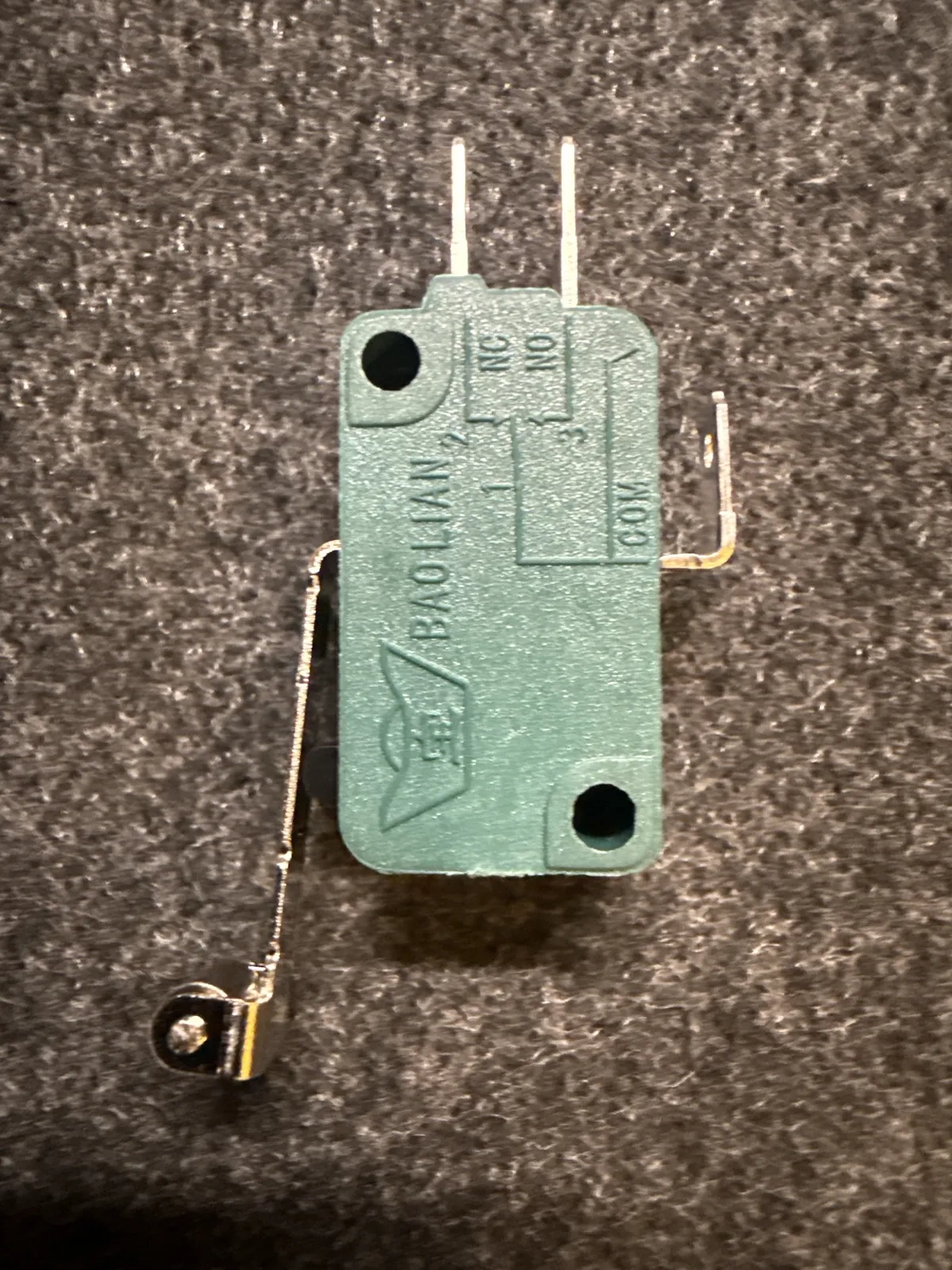
The switch has three terminals: NC and NO (normally closed, normally open) on the end, and COM (common) bent over on the side. The end tabs stick out 10.6 mm, too long for the space between the switch and the clock, which now lies across the grip just below it.
I only need COM and NO, so I’ll cut NC off and trim NO to 7 mm.
Reviewing before printing
I didn’t want to waste more than one or two prints, so I had Claude review the design and try to break it. It found:
- With print tolerances, the switch might never click. A full pull now goes 0.9 mm past the click and stops 0.5 mm before it bottoms out.
- A printed pin holding the switch would snap. It’s an M3 × 14 screw now.
- The walls around one nut were 0.17 mm thick, so the posts got bigger.
- The trigger’s stop ear would likely snap. It’s twice the size now, and the trigger gets printed solid.
- The laser hole was 10.4 mm for a 10.1 mm laser, and printed holes come out small. It’s 10.7 now.
- The clock-to-screen cable was too short. It needs 200 mm, not 100.
- Nothing held the screen in place.
To test the trigger without printing both halves, there’s a small test print, test-trigger.stl: the top of the grip with the hinge, the switch posts and the trigger’s stop. Under an hour with the trigger. If the switch doesn’t click, I sand the stop post; if it bottoms out, I add tape.
The last checks
Before printing the halves:
- Everything at the Feather’s antenna end is under 2 mm, so the switch clears it. I can’t use an external antenna on its u.FL socket, though.
- The wheel is centered on the switch, so either side can face the middle.
- The clock’s cables bend right at the plug, so they fit beside it.
For the screen, I wanted something that holds it without glue so I can take it out again. It now slides into four small slots at its corners and comes out when you open the case.
Where v0.4 ended up
- Trigger: 14 mm wide and centered, 3 mm wider inside the grip under the switch’s wheel.
- Switch: upside down beside the Feather, held by two M3 screws, one with a nut and one as a pin. Wired COM and NO.
- Clock: across the grip, low on the right wall.
- Thermal camera: flush on a 20 mm square of perfboard.
- Laser: along the top of the head.
- Screen and menu button: lower on the back. The screen sits in corner slots, no glue.
- USB-C: no cover. The port stays open in the bottom of the grip.
- Margins: the trigger is 2 mm from everything, and the switch is 1 mm from the Feather.
Next
- Print the test piece (test-trigger.stl) and the trigger (trigger.stl). Check that the switch clicks before the stop post and that the trigger springs back without rattling, then tune the model.
- Order the 200 mm cable.
- Print the two halves and the button cap at the library, and put it together.
The test print gets its own post. The changes are in PR #2, and the model is enclosure.scad.